Automatic debugging method and system of optical module
A technology of optical module testing and optical module, applied in transmission system, transmission monitoring/testing/fault measurement system, electromagnetic wave transmission system, etc. Dependence on skilled workers, reducing the participation of human factors, and improving production efficiency
- Summary
- Abstract
- Description
- Claims
- Application Information
AI Technical Summary
Problems solved by technology
Method used
Image
Examples
Embodiment Construction
[0059] The content and functions of the present invention will be described in detail below in conjunction with the accompanying drawings and embodiments.
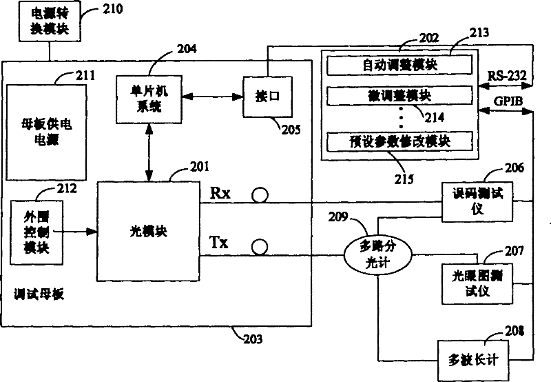
[0060] figure 2 It is a hardware system for automatic debugging of optical modules, mainly composed of optical module 201, main control computer 202, debugging motherboard 203, single-chip microcomputer system 204, interface 205, bit error tester 206, optical eye diagram tester 207, multi-wavelength meter 208, It consists of a multi-channel spectrometer 209 , a power conversion module 210 , a motherboard power supply 211 and a peripheral control module 212 .
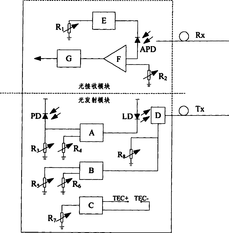
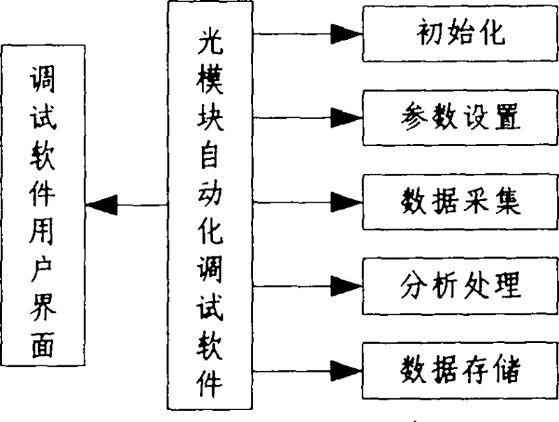
[0061] The optical module 201 to be debugged has a digital adjustment function; the main control computer 202, the optical module automatic debugging software specifically includes: an automatic adjustment module 213, a micro-adjustment module 214 and a preset parameter modification module 215, etc.; a debugging motherboard 203 Carrying the optical module 201 and o...
PUM
 Abstract
Description
Claims
Application Information
 - R&D
- Intellectual Property
- Life Sciences
- Materials
- Tech Scout
- Unparalleled Data Quality
- Higher Quality Content
- 60% Fewer Hallucinations
Browse by: Latest US Patents, China's latest patents, Technical Efficacy Thesaurus, Application Domain, Technology Topic, Popular Technical Reports.
© 2025 PatSnap. All rights reserved.Legal|Privacy policy|Modern Slavery Act Transparency Statement|Sitemap|About US| Contact US: help@patsnap.com


