
Substrate processing apparatus

A substrate processing device and substrate technology, applied to the surface coating liquid device, optics, instruments, etc., to achieve the effect of suppressing the amount of calculation processing and improving accuracy

Active Publication Date: 2011-09-14
DAINIPPON SCREEN MTG CO LTD
View PDF1 Cites 0 Cited by
  • Summary
  • Abstract
  • Description
  • Claims
  • Application Information

AI Technical Summary

Problems solved by technology

Therefore, there is a problem that the pressure measured by such a pressure sensor is a value affected by a primary delay, and when used for actual control, it is necessary to perform calculations taking this delay into consideration.

Method used


Image

  • Substrate processing apparatus
  • Substrate processing apparatus
  • Substrate processing apparatus

Examples


no. 1 approach

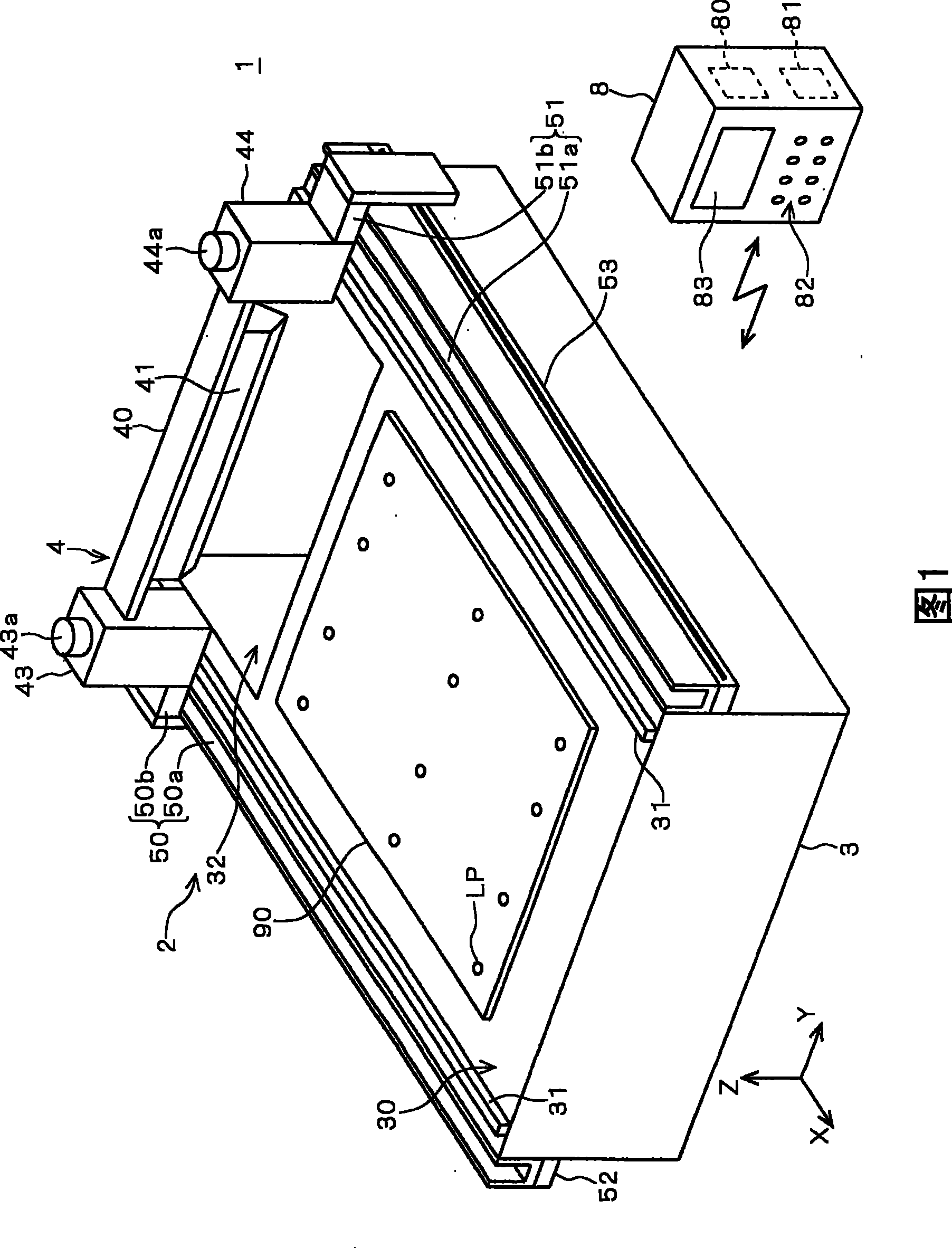
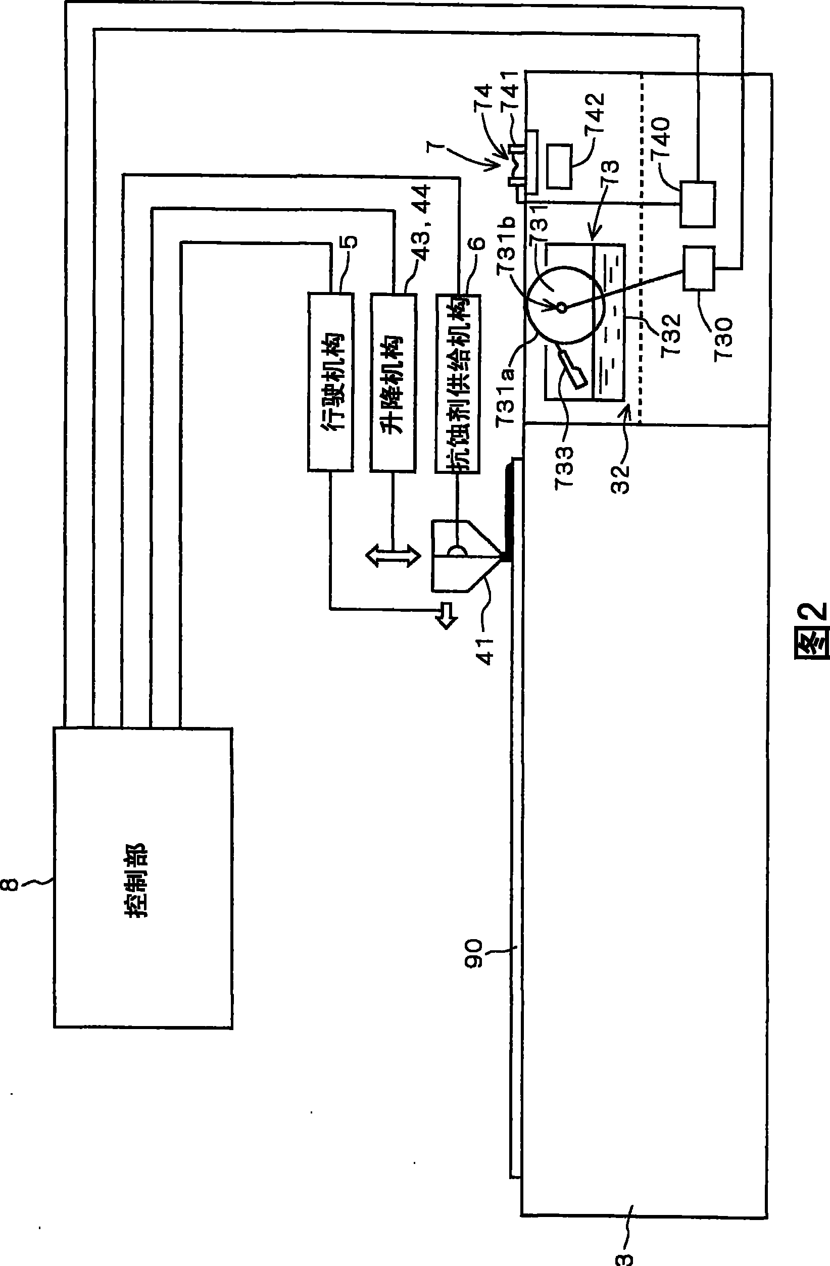
[0032] figure 1 Is a perspective view showing the outline of the substrate processing apparatus 1 of the present invention, figure 2 It is a figure which shows the side cross section of the main body 2 of the substrate processing apparatus 1, and shows the main components related to the coating operation of a resist liquid.

[0033] in figure 1 For the convenience of illustration and description, it is defined as: the Z axis direction represents the vertical direction, and the XY plane represents the horizontal plane. However, these are defined to facilitate the understanding of the positional relationship and are not limited to the directions described below. The same applies to the following drawings.

[0034] The substrate processing apparatus 1 is roughly divided into a main body 2 and a control unit 8. The square glass substrate used to manufacture the screen panel of the liquid crystal display device is used as a substrate to be processed (hereinafter referred to as "substr...

no. 2 approach

[0120] In the first embodiment, in the control value acquisition step (step S11), not only the control value of the pump 61 but also the control value of the traveling mechanism 5 is set. That is, the control value of the traveling mechanism 5 is also set in advance before the coating process.

[0121] However, in the coating process (step S13), the pressure sensor 413 may always perform measurement, and the traveling mechanism 5 may be controlled to follow the measurement value when the coating starts. That is, every time the coating process is executed, the traveling mechanism 5 may be controlled based on the measurement result of the pressure sensor 413.

[0122] Even with such a configuration, the same effect as the first embodiment can be obtained.

[0123]


PUM


Abstract

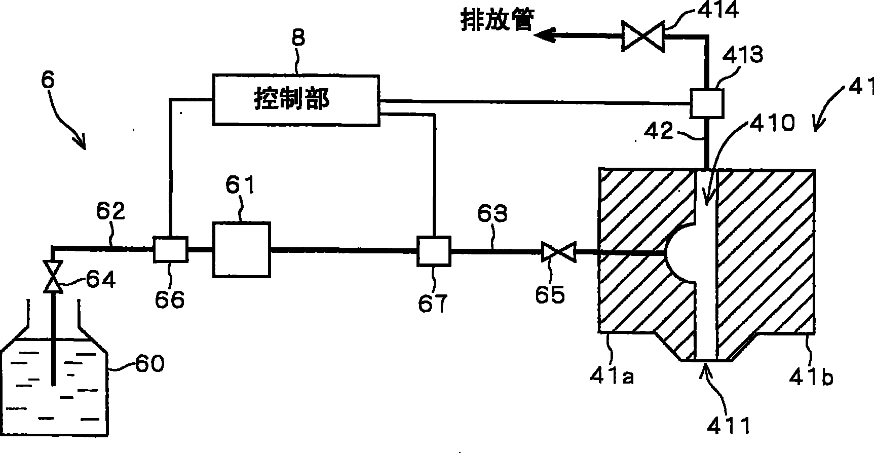
The invention relates to a substrate processing device which can measure the state of the processing liquid sprayed from a slit nozzle accurately. The invention is provided with a pipe (42) for extracting air at the secondary side of the slit nozzle (41). The pipe (42) is independent instead of directly communicating with the pipe (63) positioned at the first side of the slit nozzle (41). Besides, the pipe (42) is directly communicated with a stream (410) inside the slit nozzle (41). The pipe (42) is provided with a pressure sensor (413) so as to transfer the measure value to a control part (8). The corrosion resistance liquid is supplied to the slit nozzle (41) through a pump (61) and the pressure inside the pipe (42) at this time is measured through the pressure sensor (413).

Description

Technical field [0001] The present invention relates to a technique for controlling the discharge of a processing liquid in a slit coater, and more specifically, to a measurement technique for performing accurate control. Background technique [0002] It is known to coat the surface of glass square substrates for liquid crystals, semiconductor wafers, flexible substrates for thin film liquid crystals, substrates for photomasks, substrates for color filters, etc. (hereinafter referred to as "substrates") with processing solutions such as photoresist Coating device. As the coating device, for example, there is a slit coater that performs slit coating using a slit nozzle having a slit-shaped ejection portion. In a slit coater, since variations in coating film thickness (uniform coating) cause variations in wiring width, control of coating film thickness (uniformity) is a particularly important element. [0003] The slit coater ejects the resist from the slit nozzle, and at the same ...

Claims


Application Information

Patent Timeline
Patent Type & Authority Patents(China)
IPC IPC(8): B05C11/02B05C11/10
CPCB05C5/0258G02F1/1303H01L21/6715H01L21/67253
Inventor 高木善则冈田广司
Owner DAINIPPON SCREEN MTG CO LTD
Learn More