Beam type energy-saving oil pumping machine

An oil pumping unit and beam-type technology, which is applied in the field of energy-saving beam-type oil pumping units, can solve problems such as difficulty in saving energy, and achieve the effect of saving energy.

Inactive Publication Date: 2008-05-21
樊世耀 +2
View PDF0 Cites 7 Cited by
  • Summary
  • Abstract
  • Description
  • Claims
  • Application Information

AI Technical Summary

Problems solved by technology

[0003] The present invention aims at the problem that the existing beam pumping unit is difficult to achieve real energy saving due to the limitations of the working principle and structure, especially the limited understanding of th

Method used


Image

  • Beam type energy-saving oil pumping machine
  • Beam type energy-saving oil pumping machine
  • Beam type energy-saving oil pumping machine

Examples


Example Embodiment

[0020] Example 1

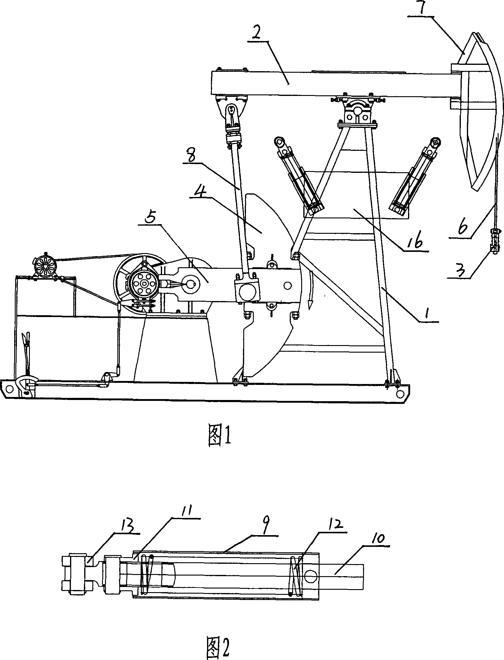
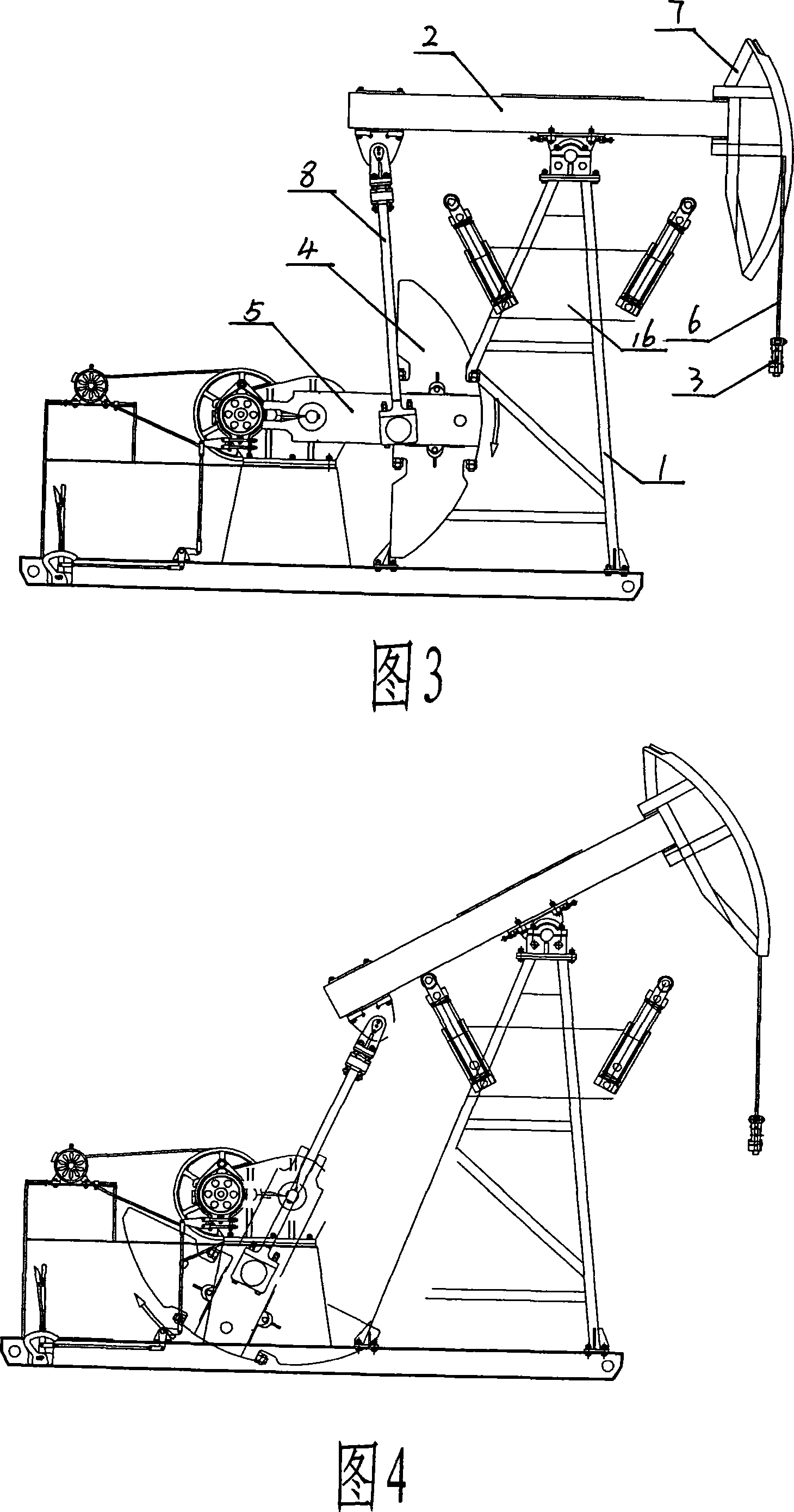
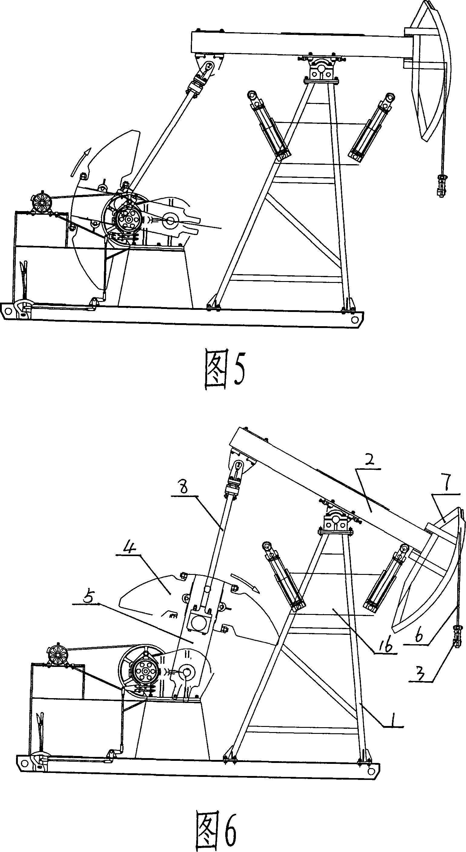
[0021] As shown in Figures 1-6, the beam-type energy-saving pumping unit includes a central support 1, a beam 2 arranged on the top of the central support 1, a pump rod 3, and one end driven and rotated by a motor and a reducer. The crank 5 of the balance weight 4, the end of the beam 2 is fixed with the donkey head 7 connected to the oil pump rod 3 through the steel cable 6, and the other end is connected with the crank 5 through the connecting rod 8, and the energy storage and utilization is arranged under the upstream beam 2 of the central support 1 device, the energy storage and utilization device includes a support body fixed on the central support 1, a support rod 10 supported by the support body and capable of reciprocating relative to the support body in a fixed direction, and an adjustment pressure sleeve is fixed on the support rod 10 11. A spring 12 is set between the adjusting pressure sleeve 11 on the support rod 10 and the supporting fixed body...

Example Embodiment

[0024] Example 2

[0025] As shown in Figures 7 and 8, the beam-type energy-saving pumping unit includes a central support 1, a beam 2 arranged on the top of the central support 1, an oil pump rod 3, and one end driven by a motor and a reducer is fixed with a The crank 5 of the balance weight 4, the end of the beam 2 is fixed with the donkey head 7 connected to the oil pump rod 3 through the steel cable 6, and the other end is connected with the crank 5 through the connecting rod 8, and the energy storage and utilization is arranged under the upstream beam 2 of the central support 1 device, the energy storage and utilization device includes a support body fixed on the central support 1, a support rod 10 supported by the support body and capable of reciprocating relative to the support body in a fixed direction, and an adjustment pressure sleeve is fixed on the support rod 10 11. A spring 12 is set between the adjusting pressure sleeve 11 on the support rod 10 and the supportin...

Example Embodiment

[0026] Example 3

[0027]As shown in Figures 9 and 10, the beam-type energy-saving pumping unit includes a central support 1, a beam 2 arranged on the top of the central support 1, a pump rod 3, and a balance fixed at one end driven by a motor and a reducer. The crank 5 of the block 4, the donkey head 7 connected to the oil pump rod 3 through the steel cable 6 is fixed at one end of the beam 2, and the other end is connected with the crank 5 through the connecting rod 8, and an energy storage and utilization device is arranged under the upstream beam 2 of the central support 1 The energy storage and utilization device includes a support body fixed on the central support 1, a support rod 10 supported by the support body and capable of reciprocating relative to the support body in a fixed direction, and an adjustment pressure sleeve 11 is fixed on the support rod 10 , A spring 12 is sleeved between the adjusting pressure sleeve 11 on the support rod 10 and the supporting fixed b...


PUM


Abstract

The present invention relates to an oil pumping machine used in oil field, in particular to an energy-saving beam oil pumping machine, which solves the problem that the prior beam oil pumping machine is difficult to achieve the energy saving due to the restrictions of the work principle and structure, in particular to the limited realization of operating mechanism. The present invention includes a central bracket, a beam, an oil pumping rod and a crank fixed with a balanced block on one end and driven by a motor and a reducer. One end of the beam is provided with a donkey head and the other end is connected with the crank through a connecting rod; an energy storage and utilization device is arranged below the upper beam of the central bracket; the energy storage and utilization device includes a support fixed body arranged on the central bracket, a support rod supported by the support fixed body reciprocating along a fixed direction against the support fixed body, a regulating jacket fixed on the support rod and a spring arranged between the regulating jacket and the fixed body on the support rod. The present invention with simple and reasonable structure and good energy-saving effect is suitable for all balanced beam oil pumping machines.

Description

technical field [0001] The invention relates to an oil pumping machine used in an oil field, in particular to a beam-type energy-saving pumping machine. Background technique [0002] The existing beam pumping unit comprises a central support, a beam arranged on the top of the central support, an oil pump rod, and a crank with a balance weight fixed at one end driven by a motor and a reducer. The cable is connected to the donkey head of the oil pump rod, and the other end is connected to the crank through the connecting rod. Driven by the motor and the reducer, the crank drives the balance block to run continuously, drives the beam to reciprocate up and down with the top of the central bracket as the center of rotation through the connecting rod, and then drives the oil well pump rod to reciprocate vertically up and down through the donkey head and the steel cable to realize Extraction of crude oil from deep formations. The general theory holds that the energy loss of the b...

Claims


Application Information

Patent Timeline
IPC IPC(8): E21B43/00F16H37/12
Inventor 樊世耀任晓明梁新文
Owner 樊世耀
Why Eureka
Try Eureka