
Anilox roller printing device

A technology of printing device and anilox roller, which is applied in printing, printing machine, rotary printing machine, etc., and can solve problems such as manufacturing tolerances

Inactive Publication Date: 2008-05-28
HEIDELBERGER DRUCKMASCHINEN AG
View PDF4 Cites 7 Cited by
  • Summary
  • Abstract
  • Description
  • Claims
  • Application Information

AI Technical Summary

Problems solved by technology

[0006] Background Art One problem that has not been solved should be the manufacturing tolerance of the diameter of the pillow ring of the mesh roll

Method used


Image

  • Anilox roller printing device
  • Anilox roller printing device
  • Anilox roller printing device

Examples


Embodiment Construction

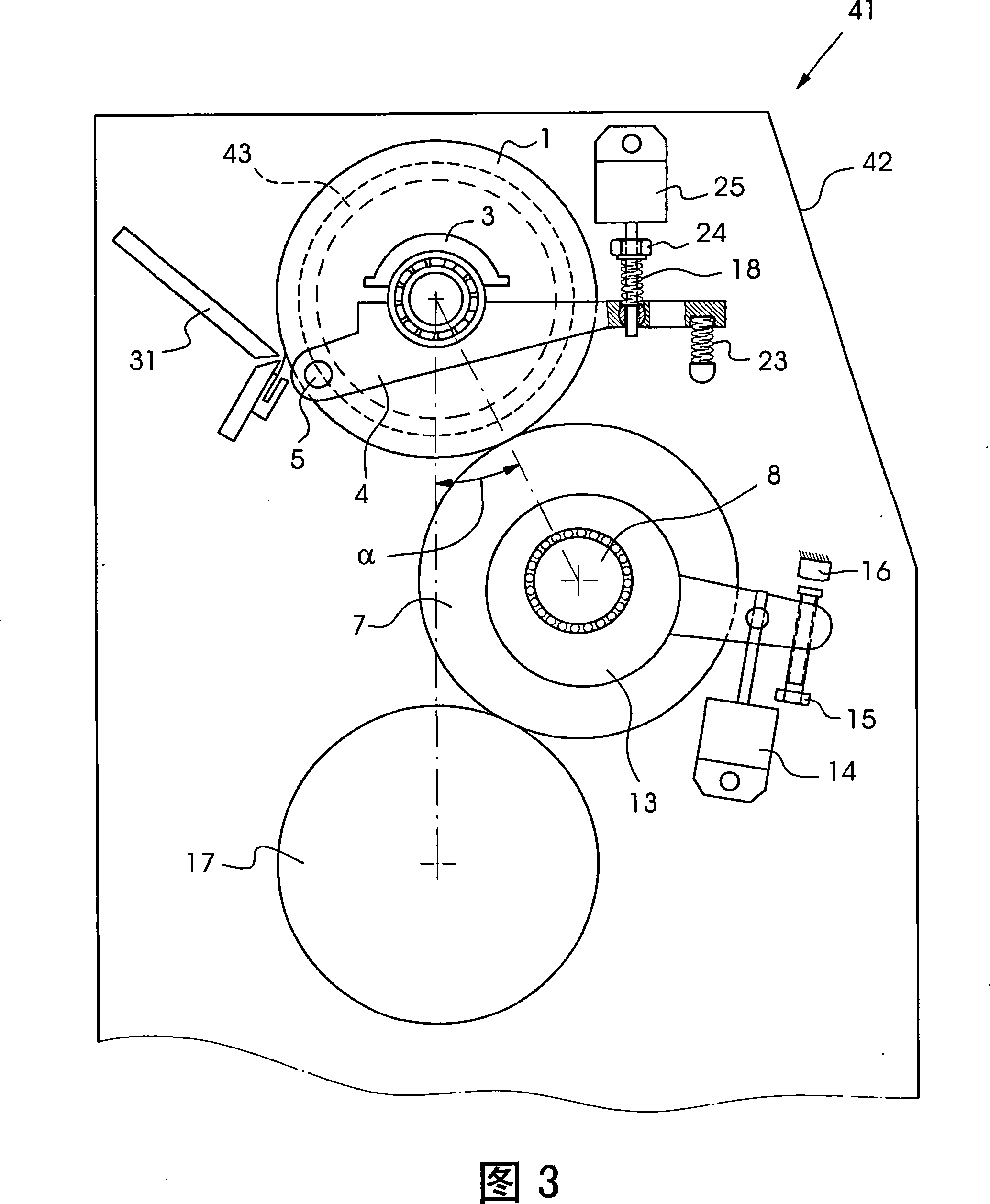
[0029] In FIGS. 1 to 5 , components and elements corresponding to each other are marked with the same reference numerals.

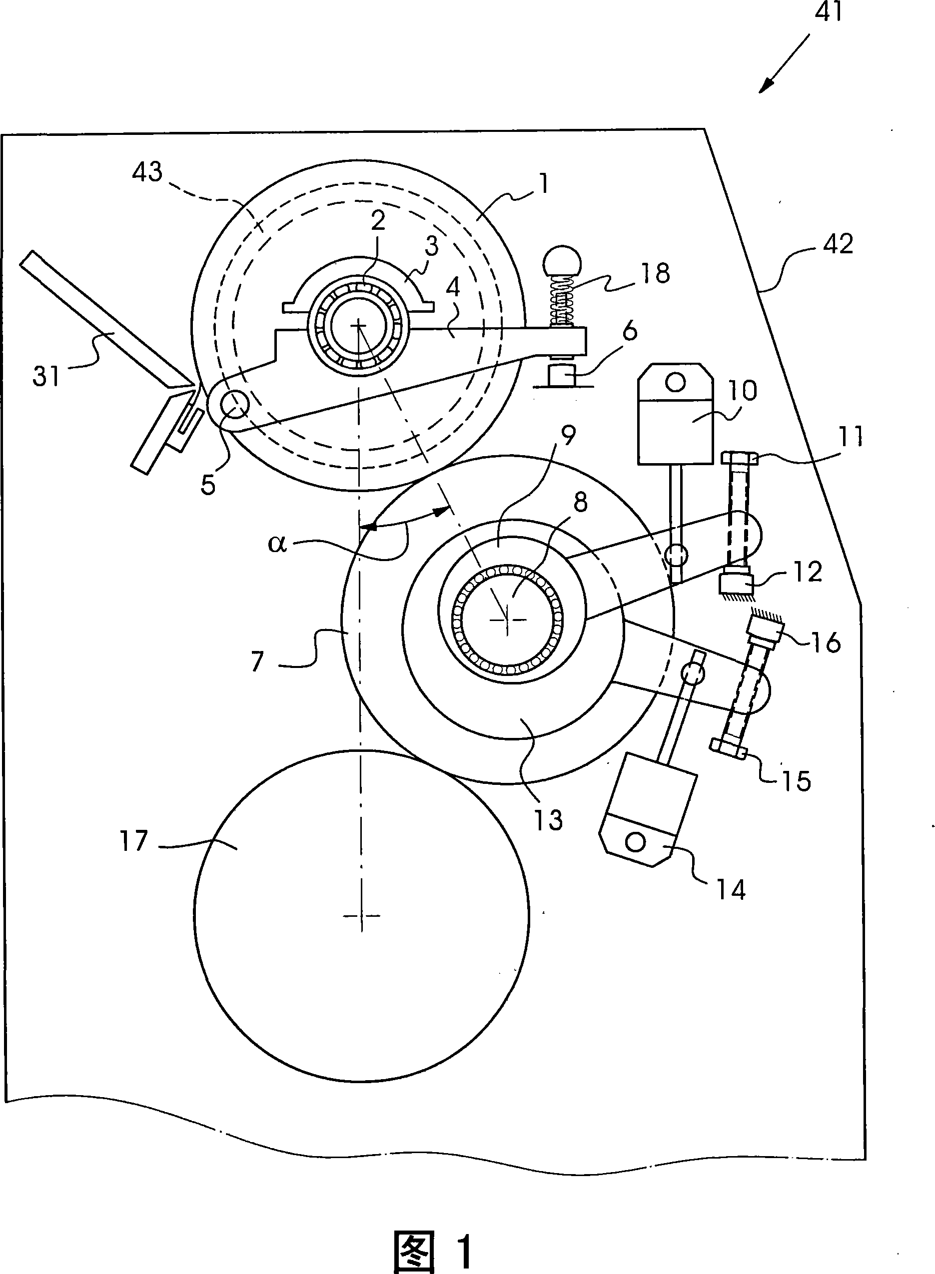
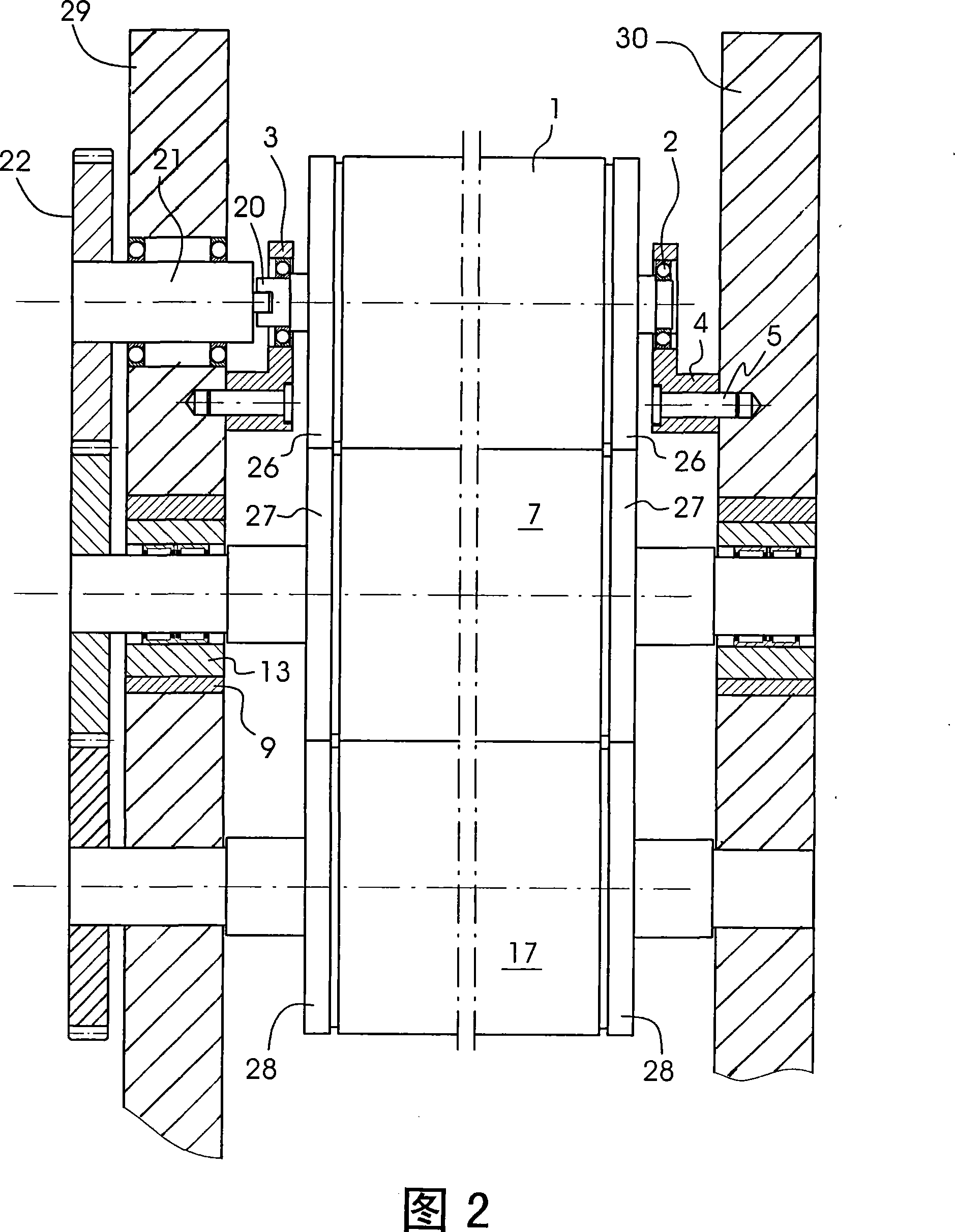
[0030] A printing press 41 is partially shown in FIGS. 1 and 2 . This detail shows an anilox printing unit 42 of a printing press 41 . The anilox printing unit 42 includes an anilox roller 1 , an ink form roller 7 and a printing plate cylinder 17 . Furthermore, the anilox printing unit 42 includes a blanket cylinder and an impression cylinder, which are not shown in the drawing. A doctor blade type ink fountain 31 rests on the screen roll 1 in order to supply the screen roll 1 with printing ink.

[0031] Mounted on the journals of the engraved roller 1 are pivot bearings 2 , which are mounted detachably by the operator in roller locks 3 . The rolling bearing 2 is a rolling bearing. The roller locks 3 are each arranged on a pivot lever 4 pivotable about a hinge 5 . Each pivot lever 4 is loaded by a spring 18 , which is supported with one end on the pi...


PUM


Abstract

The invention relates to an anilox printing unit (42) comprising an inking roller (7) and an anilox roller (1) as inking rollers, which are supported on roller locks configured as quick-change devices (3), whereby the operator can remove the mesh roller (1) from the roller locks (3) and insert another mesh roller into the roller locks (3), the mesh roller (1) is hollow and has a temperature regulating fluid flowing through it. The screen roller (1) and the inking roller (7) each have a pillow ring and one is provided for pressing the pillow ring of one of the two inking unit rollers (1, 7) against the two inking unit rollers (1, 7). The device on the sleeper ring of the other of the device rolls has some means for compensating the diameter difference between the sleeper ring of this screen roll (1) and the sleeper ring of said other screen roll caused by manufacturing tolerances and with A spring (18) for compensating the thermally induced diameter change of the pillow ring of the mesh roll (1).

Description

technical field [0001] The invention relates to an anilox roller printing device, which comprises an ink forming roller and an anilox roller. Background technique [0002] DE 10 2005 049 176 A1 describes an anilox printing unit which comprises an ink form roller and an anilox roller. The screen roll is hollow and has a temperature-regulating fluid flowing through it, and is supported in some roll locks configured as quick-change devices or quick locks, so that the screen roll can be quickly removed from the roll by the operator of the printing press. The lock and the press are removed and reinstalled. This is advantageous with regard to the maintenance of the screen roll, whose screen structure can only be thoroughly cleaned outside the printing press, taking place outside the printing press. Furthermore, a roller lock configured as a quick change device is advantageous in terms of changing the engraved roller from printing job to printing job. For example, the screen str...

Claims


Application Information

Patent Timeline
IPC IPC(8): B41F31/30
CPCB41F13/36B41F13/21B41F31/305
Inventor G·宾德尔S·德米尔J·米歇尔斯U·普弗勒D·沙夫拉特J·席尔法尔特W·舍恩贝格尔B·施瓦布M·蒂勒曼
Owner HEIDELBERGER DRUCKMASCHINEN AG
Learn More