Thermoplastic polyurethane (TPU) film slitter guide roller mechanism

A slitter and guide roller technology, applied in metal processing, sending objects, thin material processing, etc., can solve the problems of inability to limit, unable to adjust the limit, difficult to adjust the tension of the guide rod, to avoid re-adjustment , The effect of preventing deviation and improving work efficiency

Pending Publication Date: 2021-04-02
浙江长鸿纺织科技有限公司
View PDF0 Cites 0 Cited by
  • Summary
  • Abstract
  • Description
  • Claims
  • Application Information

AI Technical Summary

Problems solved by technology

[0004] Aiming at the deficiencies of the prior art, the present invention provides a guide roller mechanism for a TPU film slitting machine, which solves the problems that the existing guide rollers are difficult to adjust the tension, cannot be limited, and cannot be adjusted according to different needs

Method used


Image

  • Thermoplastic polyurethane (TPU) film slitter guide roller mechanism
  • Thermoplastic polyurethane (TPU) film slitter guide roller mechanism
  • Thermoplastic polyurethane (TPU) film slitter guide roller mechanism

Examples


Embodiment 1

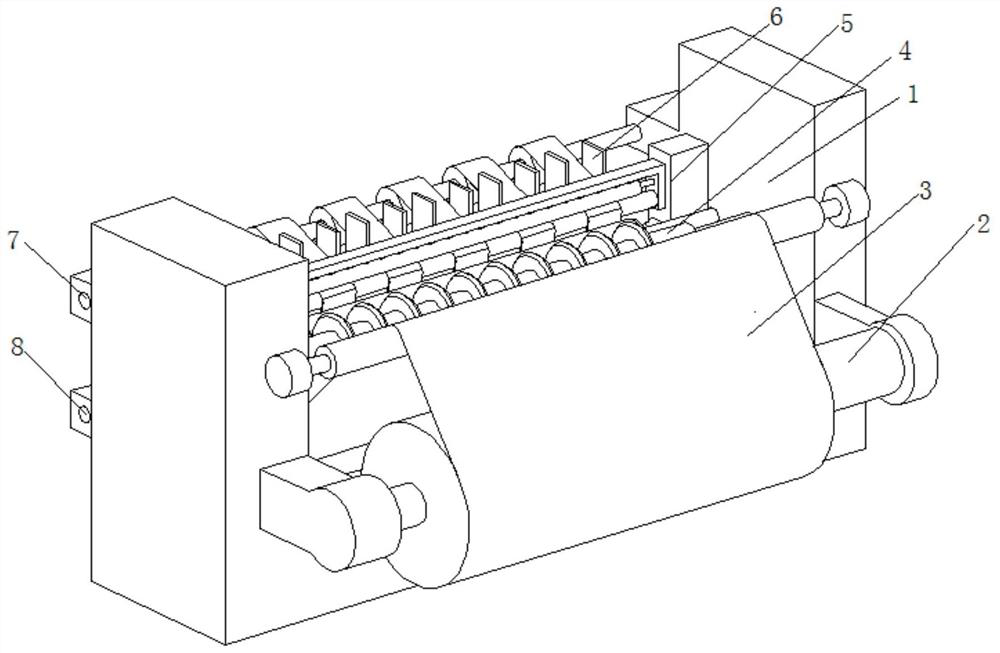
[0031] A TPU film slitting machine guide roller mechanism, such as Figure 1-Figure 5 As shown, it includes a body 1, the front of the body 1 is rotatably connected to a feed roller 2, the surface of the feed roller 2 is fixedly connected to a film roll body 3, and the inside of the body 1 is rotatably connected to a knife roller 4, and the body 1 is located on the knife roller The rear part of 4 is provided with adjusting mechanism 5, and the surface of adjusting mechanism 5 is provided with guiding mechanism 6, and body 1 is positioned at the rear portion of adjusting mechanism 5 and is respectively connected with upper receiving roller 7 and lower receiving roller 8, and upper receiving roller The roll 7 is located above the lower take-up roll 8 .

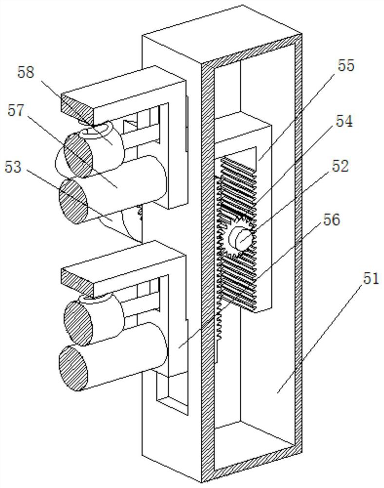
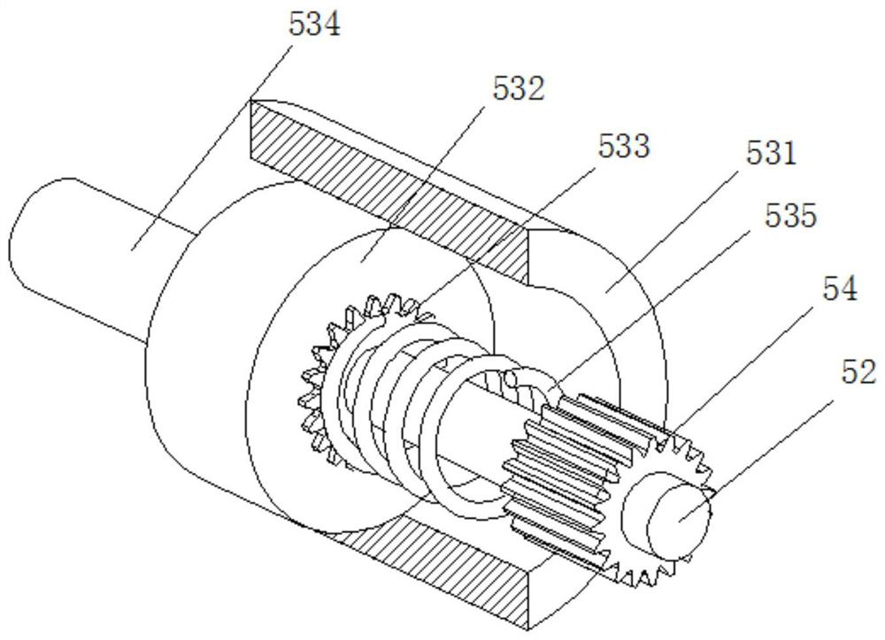
[0032] In this embodiment, the adjustment mechanism 5 includes an adjustment box 51, the right side of the adjustment box 51 is fixedly connected to the surface of the body 1 by bolts, the inside of the adjustment box 51 is conn...

Embodiment 2

[0042] like Figure 6-Figure 7 As shown, on the basis of Embodiment 1, in this embodiment, the guide mechanism 6 includes a base 61, the top of the base 61 is welded and fixed to the surface of the lead roller 57, and the inner wall of the base 61 is rotatably connected to a shaft 62, the shaft The surface of 62 is welded with adjustment gear 63, and the surface of adjustment gear 63 is engaged with front tooth plate 64 and rear tooth plate 65 respectively, and the rear end of front tooth plate 64 and rear tooth plate 65 is welded with right guide plate 66 and left guide plate 67 respectively, And the bottoms of the front tooth plate 64 and the rear tooth plate 65 are all slidably connected with the bottom of the inner wall of the base 61, the inside of the base 61 is provided with an interlocking device 68, and the shape of the right guide plate 66 and the left guide plate 67 is set to Z.

[0043] The folding state achieves the effect of limiting the slitting film on the guid...


PUM


Abstract

The invention relates to the technical field of slitter guide rollers, and discloses a thermoplastic polyurethane (TPU) film slitter guide roller mechanism. The TPU film slitter guide roller mechanismcomprises a machine body; the front portion of the machine body is rotatably connected with a feeding roller; the surface of the feeding roller is fixedly connected with a film roll body; the interior of the machine body is rotatably connected with a knife roller; an adjusting mechanism is arranged at the position, located behind the knife roller, of the machine body; the surface of the adjustingmechanism is provided with a guide mechanism; an upper take-up roller and a lower take-up roller are rotatably connected to the portion, located on the rear portion of the adjusting mechanism, of themachine body; and the upper take-up roller is located above the lower take-up roller. According to the TPU film splitter guide roller mechanism, by installing the adjusting mechanism and the guide mechanism, the effect of adjusting the tension degree of the guide roller is achieved through mutual operation of all structures in the adjusting mechanism and the guide mechanism, and meanwhile, the effect that split film bodies different in thickness can be pressed is achieved when the tension degree is adjusted, thereby achieving the effect of guiding the film bodies different in cutting width tobe conveyed.

Description

technical field [0001] The invention relates to the technical field of slitter guide rollers, in particular to a TPU film slitter guide roller mechanism. Background technique [0002] The slitting machine is a kind of mechanical equipment that cuts wide paper, mica tape or film into multiple narrow-width materials. It is often used in papermaking machinery, wire and cable mica tape and printing and packaging machinery. The slitter is mainly used in non-woven fabrics. Slitting of cloth / mica tape, paper, insulating material and various film materials, especially suitable for slitting of narrow tape (non-woven fabric, paper, insulating material, mica tape, film, etc.), TPU film is thermoplastic TPU elastomer It is made of MDI containing NCO functional group and POLYOL and 1.4BG containing OH functional group through extrusion and mixing. Due to its good elasticity, good physical properties and good mechanical strength, it is widely used in injection, Processing methods such as...

Claims


Application Information

Patent Timeline
Patent Type & Authority Applications(China)
IPC IPC(8): B26D7/06B26D7/08B26D7/14B26D1/15B65H35/02
CPCB26D1/151B26D7/0683B26D7/08B26D7/14B26D2007/082B65H35/0073B65H35/02
Inventor 付红明
Owner 浙江长鸿纺织科技有限公司
Why Eureka
Try Eureka