Novel pumping machine
What is Al technical title?
Al technical title is built by PatSnap Al team. It summarizes the technical point description of the patent document.
A pumping unit, a new type of technology, applied in the direction of mechanical equipment, mining fluid, wellbore/well parts, etc., can solve the problems of inconvenient maintenance operation, large mechanical loss, inconvenient management, etc., to achieve convenient maintenance and operation, and prolong use The effect of life, adjustment and installation convenience
Inactive Publication Date: 2012-12-26
SENUO TECH CO LTD
View PDF0 Cites 0 Cited by
Summary
Abstract
Description
Claims
Application Information
AI Technical Summary
This helps you quickly interpret patents by identifying the three key elements:
Problems solved by technology
Method used
Benefits of technology
Problems solved by technology
[0002] At present, there are many oil production equipment used in oil fields, such as beam pumping units, chain pumping units and vertical drum pumping units. These pumping units have been popularized and applied in oil fields to varying degrees, especially beam pumping units. Most of them are used, but there are many mechanical transmission links, large mechanical losses, more steel materials, troublesome stroke adjustment and stroke times, and inconvenient management. The latter two pumping units solve the troublesome problems of stroke adjustment and stroke times and long-stroke oil production Problem, but the transmission equipment of the operating equipment is set on the elevated platform, the maintenance operation is very inconvenient and not very safe, the adjustment balance is difficult to adjust, and more steel is used
Method used
Image
Click on the blue label to locate the original text in one second.
Reading with bidirectional positioning of images and text.
Examples
Embodiment Construction
[0021] In order to further disclose the technical solutions of the present invention, the following will be described in detail through examples in conjunction with the accompanying drawings:
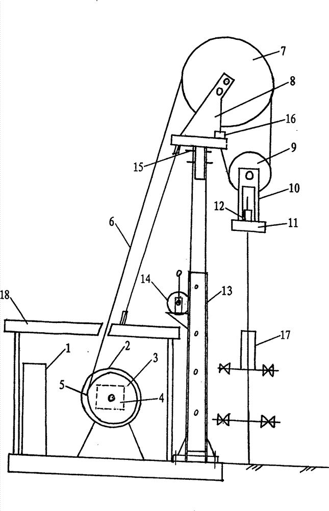
[0022] The present invention consists of a control cabinet 1, a switched reluctance motor 2, a transmission 4, a brake 5, a drum 3, a wire rope 6, a fixed pulley 7, a movable pulley 9, a fixed pulley bracket 8, a rope suspension 11, a movable pulley bracket 10 and a support frame 13. , which is characterized in that the control cabinet, the reluctance motor, the roller and the support frame are arranged on a skid placed on the ground, a fixed pulley is arranged at the upper end of the support frame, a movable pulley or a group of movable pulleys are arranged on the rope hanger, and the movable pulley bracket and The rope suspension is integrated; the control cabinet control circuit is connected with the switched reluctance motor circuit, the reluctance motor shaft is connected with the c...
PUM
Abstract
A novel pumping unit comprises a control cabinet, a switch reluctance motor, a speed-changer, a brake, a cylinder, a steel cable, a fixed block, a movable pulley, a fixed block holdfast, a polished rod eye, and a bracing frame. The control cabinet, the reluctance motor, the cylinder, and the bracing frame are arranged and placed on a prying block on the earth surface, the upper end of the bracing frame is provided with the fixed block, the movable pulley or a group of movable pulleys are arranged on the polished rod eye, the fixed block holdfast and the polished rod eye are connected in a whole. The control cabinet controls a circuit to connect with a switch reluctance motor circuit, a reluctance motor shaft is connected with an input shaft of a clutch, an output shaft of the clutch is connected with a cylinder shaft, the end of the steel cable on the cylinder is fixed on a fixed block frame through the fixed block and the moveable pulley, or which is fixed on the fixed block holdfast through an energy storage spring, or is connected with a balance box through the fixed block which is arranged on the fixed block holdfast, and the polished rod eye is connected with a polish rod through a holding latch. The invention has simple structure, lower cost, and electric energy saving.
Description
1. Technical field [0001] The invention relates to a novel pumping unit for mechanical oil recovery in oil fields. 2. Background technology [0002] At present, there are many oil production equipment used in oil fields, such as beam pumping units, chain pumping units and vertical drum pumping units. These pumping units have been popularized and applied in oil fields to varying degrees, especially beam pumping units. Most of them are used, but there are many mechanical transmission links, large mechanical losses, more steel materials, troublesome stroke adjustment and stroke times, and inconvenient management. The latter two pumping units solve the troublesome problems of stroke adjustment and stroke times and long-stroke oil production Problem, but the transmission equipment of the operating equipment is set on the elevated platform, the maintenance operation is very inconvenient, and it is not very safe. It is difficult to adjust the balance, and more steel is used. 3. C...
Claims
Application Information
Patent Timeline
Application Date:The date an application was filed.
Publication Date:The date a patent or application was officially published.
First Publication Date:The earliest publication date of a patent with the same application number.
Issue Date:Publication date of the patent grant document.
PCT Entry Date:The Entry date of PCT National Phase.
Estimated Expiry Date:The statutory expiry date of a patent right according to the Patent Law, and it is the longest term of protection that the patent right can achieve without the termination of the patent right due to other reasons(Term extension factor has been taken into account ).
Invalid Date:Actual expiry date is based on effective date or publication date of legal transaction data of invalid patent.