
DC converter valve restoration period transient forward voltage test method

A DC converter valve and forward voltage technology, which is applied in the field of power electronics and power systems, can solve problems such as inapplicability of test methods, unsatisfactory test valves, poor equivalence, etc., and achieve wide range of test products and equivalence Good, the effect of improving efficiency

Active Publication Date: 2010-06-02
CHINA ELECTRIC POWER RES INST +1
View PDF4 Cites 3 Cited by
  • Summary
  • Abstract
  • Description
  • Claims
  • Application Information

AI Technical Summary

Problems solved by technology

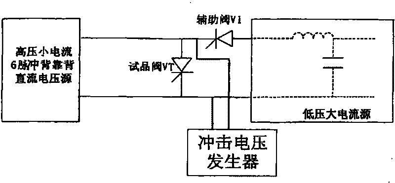
[0006] The technical problem to be solved in the present invention is that the test method for the instantaneous forward voltage during the recovery period of the existing DC converter valve cannot meet the requirements of the test valve because it cannot be carried out under the working conditions corresponding to the minimum cut-off angle required by the test. The requirements for energy extraction and poor equivalence make this test method inapplicable, and the test method needs to be changed again. The purpose of the present invention is to provide a method for instantaneous forward voltage test during DC converter valve recovery, and to accomplish the purpose of the present invention. The technical scheme adopted is as follows: a method of instantaneous forward voltage test during DC converter valve recovery, the test valve VT is used as a back-to-back 6-pulse bridge and one bridge arm is connected to the high-voltage small current source circuit, and the impulse voltage is connected in parallel at both ends of VT The generator is connected in parallel with the circuit in which the auxiliary valve V1 is connected in series with the low-voltage and high-current source. It is characterized in that the 6-pulse bridge where the test valve is located performs inverter operation, and the high-voltage small current source provides the forward trigger voltage required by the test product. and the reverse recovery voltage after the sample is turned off, and the forward voltage rise rate during the blocking period of the sample valve, and at the same time, by adjusting the high voltage and small current source, it is very convenient to adjust the current change rate before the sample valve is turned off; The low-voltage high-current source injects a half-wave sinusoidal current during the conduction period of the test valve, and reproduces the loss during the conduction period of the test valve with the correct equivalent peak value of the test valve conduction current. Before the current of the high-voltage small current source is cut off Within a few hundred microseconds, the low-voltage and high-current current crosses zero, which isolates the low-voltage and high-current loop, and at the same time ensures that the auxiliary valve is safely and reliably shut off; during the reverse recovery period and after the recovery period of the test valve, the impulse voltage is passed The generator applies an instantaneous positive voltage shock to the sample valve

Method used


Image

  • DC converter valve restoration period transient forward voltage test method
  • DC converter valve restoration period transient forward voltage test method
  • DC converter valve restoration period transient forward voltage test method

Examples


Embodiment Construction

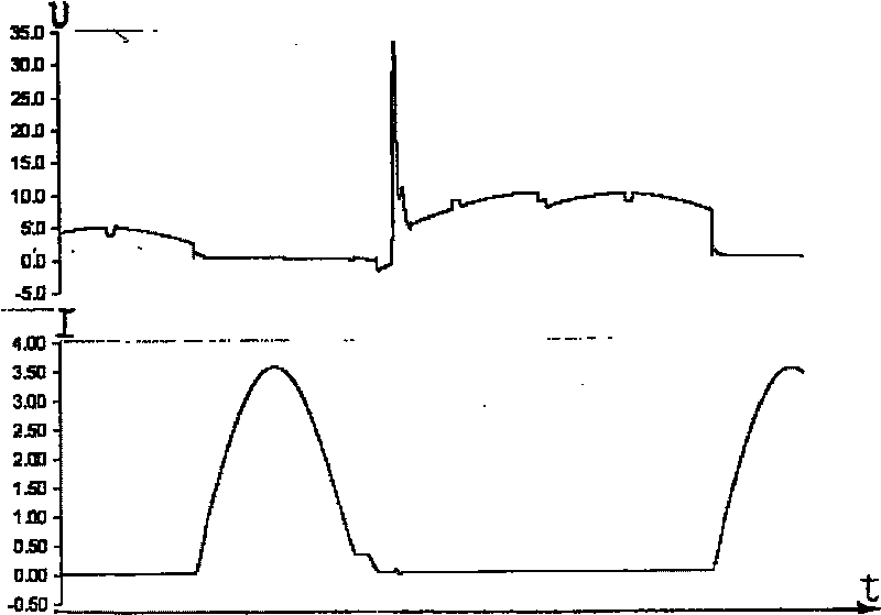
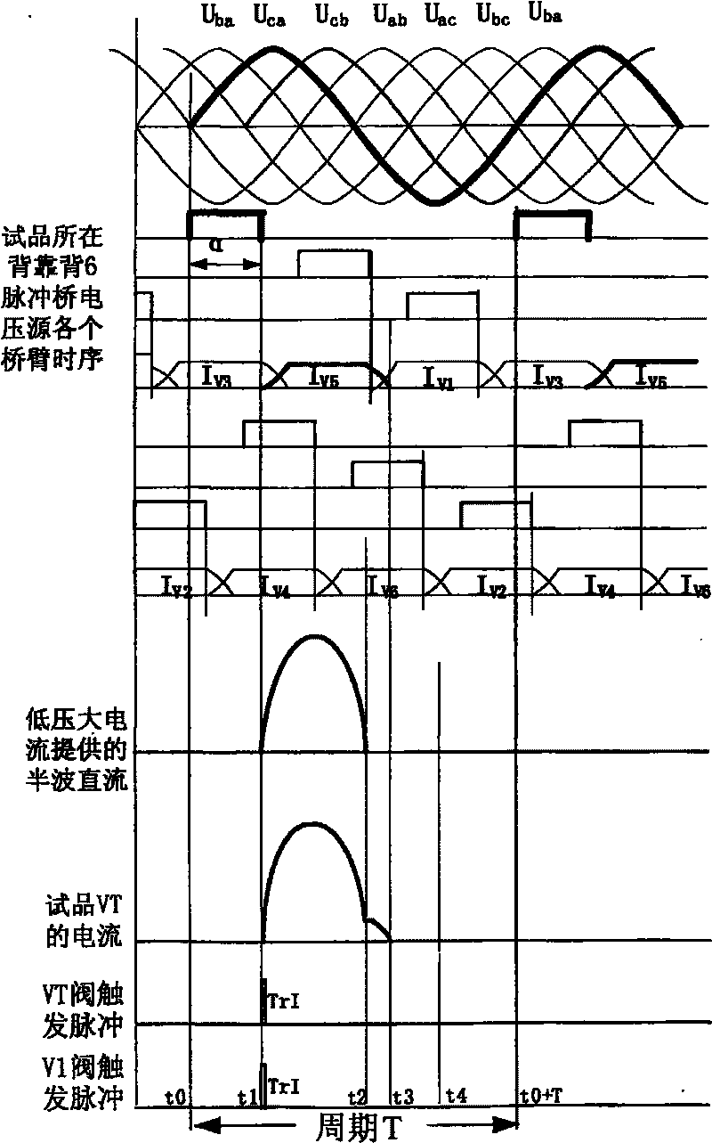
[0014] refer to figure 1 , represents the principle block diagram of the instantaneous forward voltage test during the recovery period of the DC converter valve. In the figure, the high-voltage small current source is a back-to-back 6-pulse bridge DC power supply, and VT is the test valve, which is connected in parallel with the impulse voltage generator, and then connected with the auxiliary valve V1 and The circuits connected in series with low-voltage and high-current sources are connected in parallel, and the instantaneous forward voltage test during the recovery of the DC converter valve is referenced in the connected circuits. figure 2 Shown are voltage and current waveforms obtained in the above test. refer to image 3 , represents the trigger timing diagram of pulses added in the instantaneous forward voltage test during the recovery period. The abscissa in the figure represents different periods within a test cycle, and the ordinate represents the state of each trig...


PUM


Abstract

The invention discloses a method for testing instantaneous forward voltage in a dc converting valve recovering period, which belongs to the power electronics and electric system field, and comprisesfollowing steps: taking a specimen valve VT as a back to back 6 impulse bridge whose one bridge arm is connected with a high pressure little current source circuit, connecting in series impulse voltage generators on two ends of the VT, connecting with a circuit which is connected in parallel between an auxiliary valveV1 and a low-pressure large electric current source, and adding a pulse trigger into the circuit in a testing period. A time sequence process comprises following steps:, t0-t1, controlling the 6 impulse bridge to trigger an angel alpha, operating in inversion, triggering and conducting valve VT and valve V1 through t1time, introducing a half wave direct current, a zero-crossing half wave current t2 which is from a large electric current circuit, switching off the V1, t2-t3, switching off the V1, wherein a little electric current of a valve arm which contains the VT transverses through the specimen valve, zero-crossing and switching off t3 and VT, providing specimen voltagethrough a high pressure little current source back to back circuit, t3-t4, and loading the impulse voltage on the specimen valve. The method can satisfy an energy taking requirement for the specimenvalve and have wide specimen range and good equivalence.

Description

technical field [0001] The invention belongs to the fields of power electronics and power systems, and in particular relates to a method for testing instantaneous forward voltage during recovery of a DC converter valve. Background technique [0002] The DC converter valve is the core and key equipment of DC power transmission, and the power system in which the DC converter valve itself is located is very complex. It will withstand different voltage and current stresses under various normal and fault conditions in the system. To protect the normal operation of the DC converter valve, it is required to have corresponding protection functions and bearing capacity. These capabilities need to be assessed through test methods, and the DC converter valve operation test is an important means to verify the performance of the valve. The instantaneous forward voltage test during the recovery period is an important part of the DC converter valve operation test. Applying a transient for...

Claims


Application Information

Patent Timeline
Patent Type & Authority Patents(China)
IPC IPC(8): G01R31/26G01R31/00G01R31/327
Inventor 汤广福温家良查鲲鹏贺之渊
Owner CHINA ELECTRIC POWER RES INST
Learn More