Electromagnetic drive system

An electromagnetic drive and motion technology, applied in the direction of electromagnets, electromagnets with armatures, circuits, etc., can solve the problems of large inertia and delayed response of the drive device.

Inactive Publication Date: 2008-05-28
SIEMENS AG
View PDF1 Cites 4 Cited by
  • Summary
  • Abstract
  • Description
  • Claims
  • Application Information

AI Technical Summary

Problems solved by technology

[0003] As the mass of the armature of the electromagnetic drive increases, the inertia of the entire system becomes greater and the response of the drive is delayed

Method used


Image

  • Electromagnetic drive system
  • Electromagnetic drive system
  • Electromagnetic drive system

Examples


Embodiment Construction

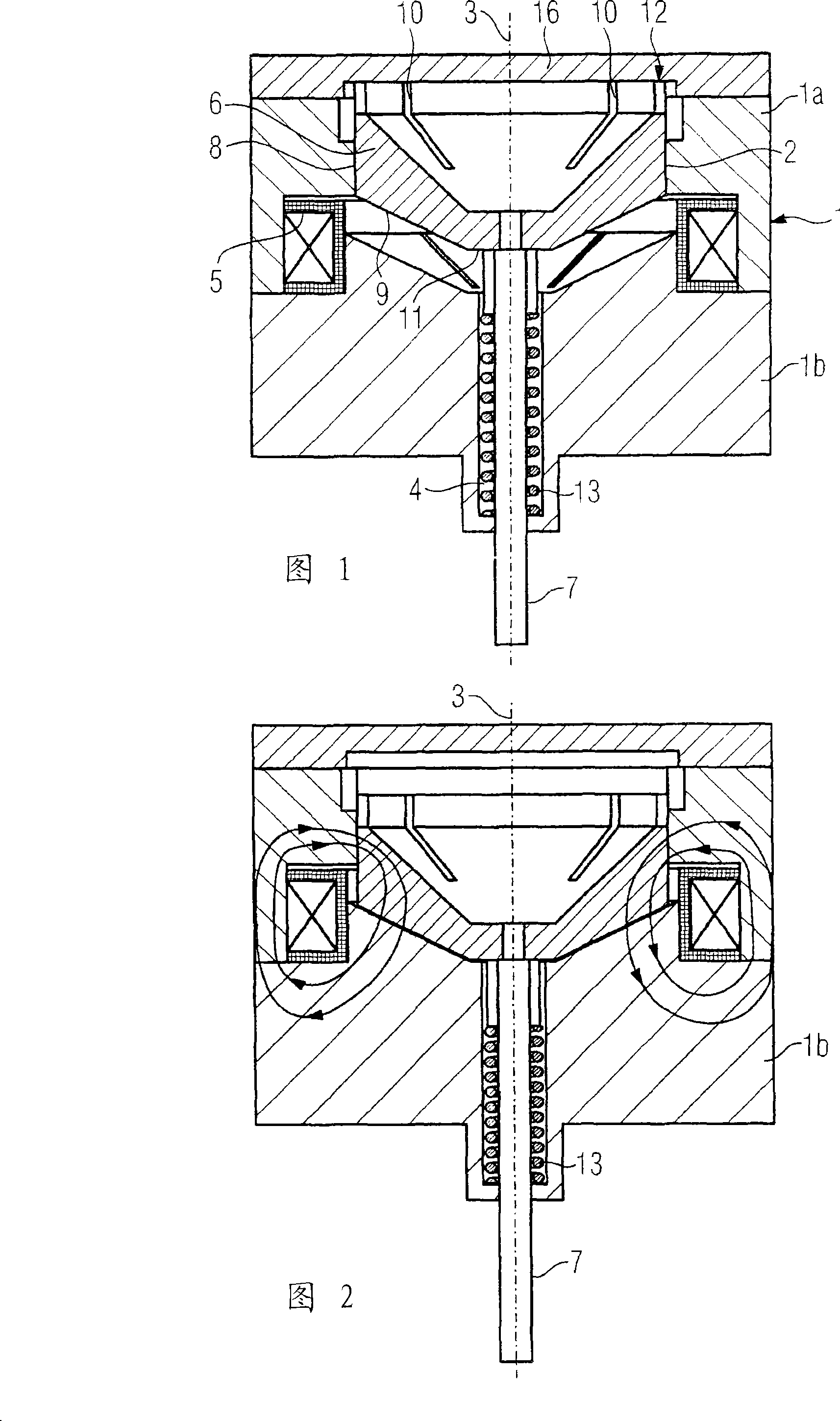
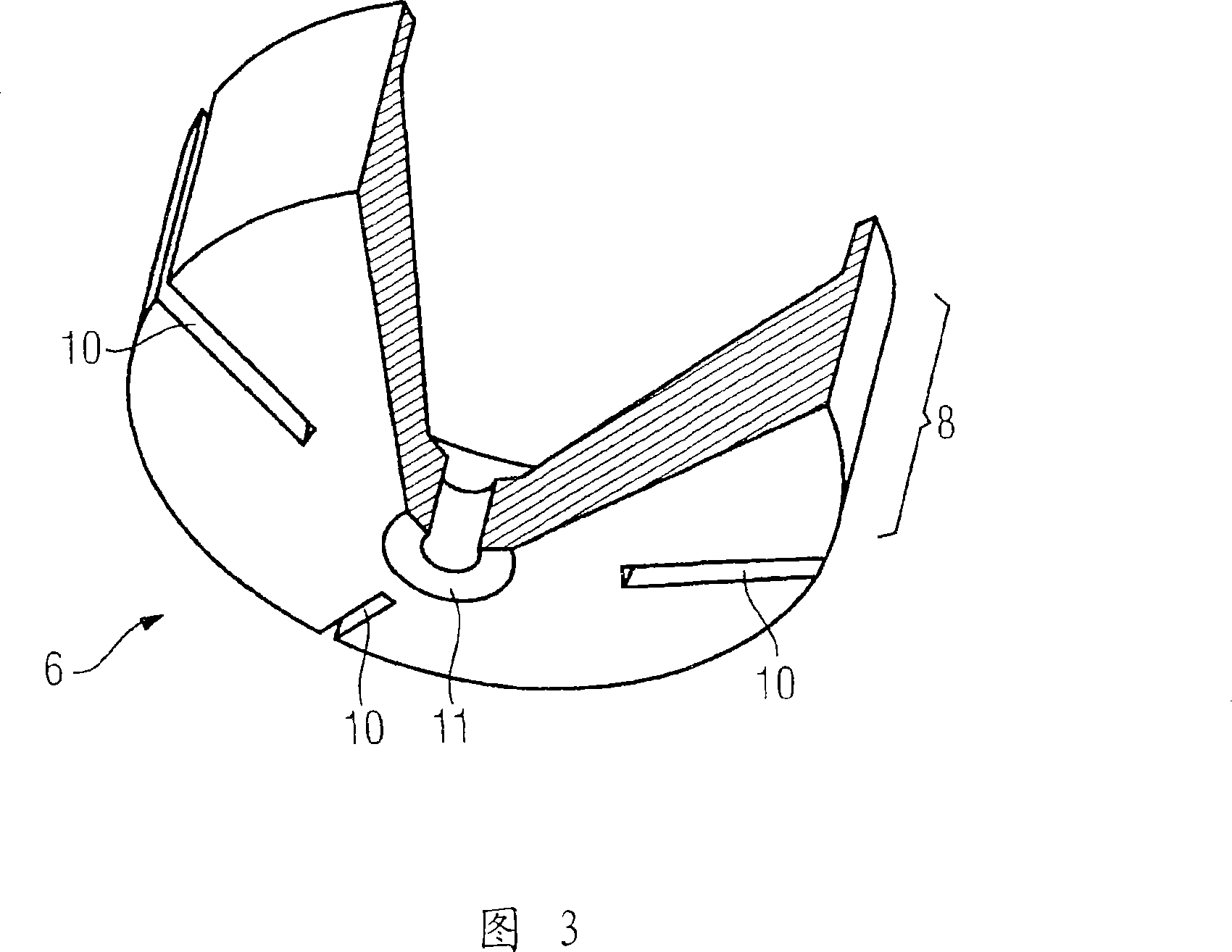
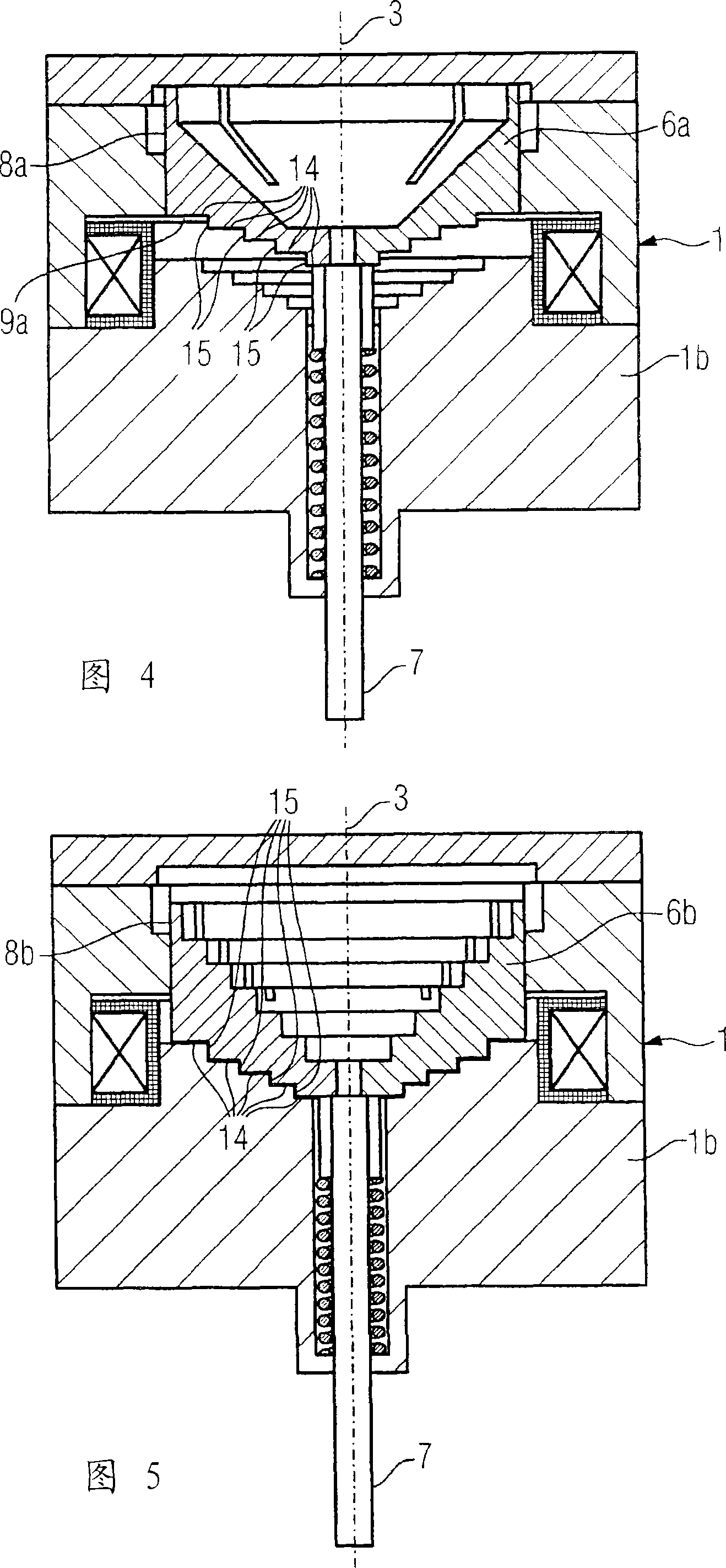
[0036]First, the principle structure of the electromagnetic drive device according to the present invention is explained by way of example with reference to FIG. 1 . The embodiments shown in FIGS. 4 and 5 are designed in principle identically, but differ in the design of the armature.

[0037] The first embodiment of the electromagnetic drive has a stator 1 . The stator 1 consists of a first part 1a and a second part 1b. The first part 1 a has a cylindrical section 2 . The cylinder section 2 has a circular cross section. The cylinder section 2 is arranged coaxially to an axis 3 . The second part 1 b of the stator 1 has a channel 4 arranged coaxially to the axis 3 and having a circular cross-section. The first part 1a and the second part 1b of the stator are connected to each other, thus creating a compact body guiding the magnetic field lines. In the stator 1 , an energizable winding 5 with an iron core is inserted into an annular gap formed in the joining region of the f...


PUM


Abstract

An electromagnetic drive system comprises an armature (6, 6a, 6b) that can be displaced along an axis (3). The armature (6, 6a, 6b) comprises a piston-shaped section (8, 8a, 8b). Said piston-shaped section (8, 8a, 8b) is guided in a cylindrical section (2) of the stator (1). A recess (10) extends through the piston-shaped section (8, 8a, 8b) substantially in the direction of the axis (3).

Description

technical field [0001] The invention relates to an electromagnetic drive having an armature displaceable along an axis, the armature having a piston-shaped section which is displaceable within a cylinder-shaped section of a stator. Background technique [0002] Such an electromagnetic drive is known, for example, from the German utility model DE 29715900U1. In this utility model an electromagnetic drive is described, which is used for triggering the switching operation of a power switch. For this purpose, the electromagnetic drive has a stator with an electromagnetic winding into which the armature can be moved when the winding is energized. The armature has a piston-shaped section that can move within the cylinder-shaped section of the stator. In order to adjust the response time of the armature, the mass of the armature is changed. [0003] As the mass of the armature of the electromagnetic drive increases, the inertia of the entire system becomes greater and the respon...

Claims


Application Information

Patent Timeline
Patent Type & Authority Applications(China)
IPC IPC(8): H01F7/16H01F7/08
CPCH01F2007/086H01F7/1607
Inventor 乔格·哈根卡斯滕·普罗泽
Owner SIEMENS AG
Why Eureka
Try Eureka