Traction machine brake

A mechanical brake and brake technology, which is applied in hoisting devices and other directions, can solve problems such as higher spring performance requirements, high processing difficulty, and magnetic steel demagnetization, and achieve high operational safety and stability, long service life, and cost reduction. Effect

Active Publication Date: 2015-02-25
GIANT KONE ELEVATOR CO LTD
View PDF6 Cites 1 Cited by
  • Summary
  • Abstract
  • Description
  • Claims
  • Application Information

AI Technical Summary

Problems solved by technology

[0002] As the driving part of the elevator, the traction machine is a device that drives the elevator car and the counterweight device to run up and down. It is mainly composed of a motor, a brake, a traction wheel, etc. The components are composed of components. As the safety component of the elevator, the brake is the basic device to ensure the safe operation of the elevator. The elevator uses a mechanical-electrical friction type normally closed brake. When the elevator is not working, the brake is applied. When the elevator is running, the brake is released. When the elevator brakes, it relies on the action of mechanical force to make the friction plate rub against the brake wheel to generate braking torque; when the elevator moves, it relies on electromagnetic force to release the brake. The requirement for the elevator brake is: it can generate enough brake The dynamic moment, when the brake is released or braked, requires stability and can meet the working requirements of frequent starting and braking; as a safety component of the elevator, the performance and cost of the brake directly determine the quality and competitiveness of the electric sample. In the prior art, most of the brakes are directly braked on the traction sheave, and the long-term action of the brakes rubs against the brake wheel to generate heat, resulting in demagnetization of the magnetic steel; there are also some brakes on the brake disc. Disc brakes are all faced with the problems of difficult adjustment and high processing difficulty, and the existing brakes directly act on the brake wheel through the elastic force generated by the spring, which requires higher performance of the spring, and the electromagnetic force generated by the brake coil It also takes more force to engage the brakes

Method used


Image

  • Traction machine brake
  • Traction machine brake
  • Traction machine brake

Examples


Embodiment 1

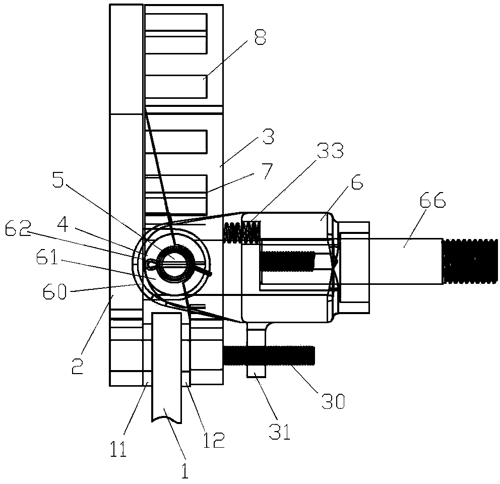
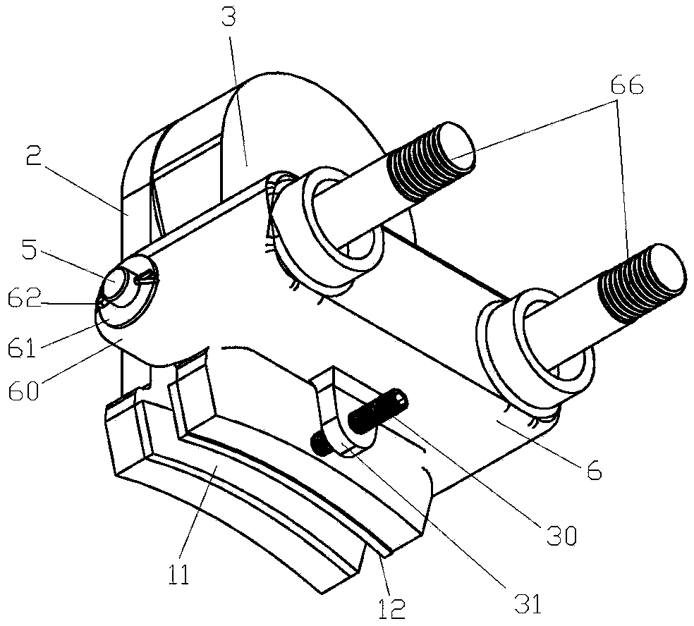
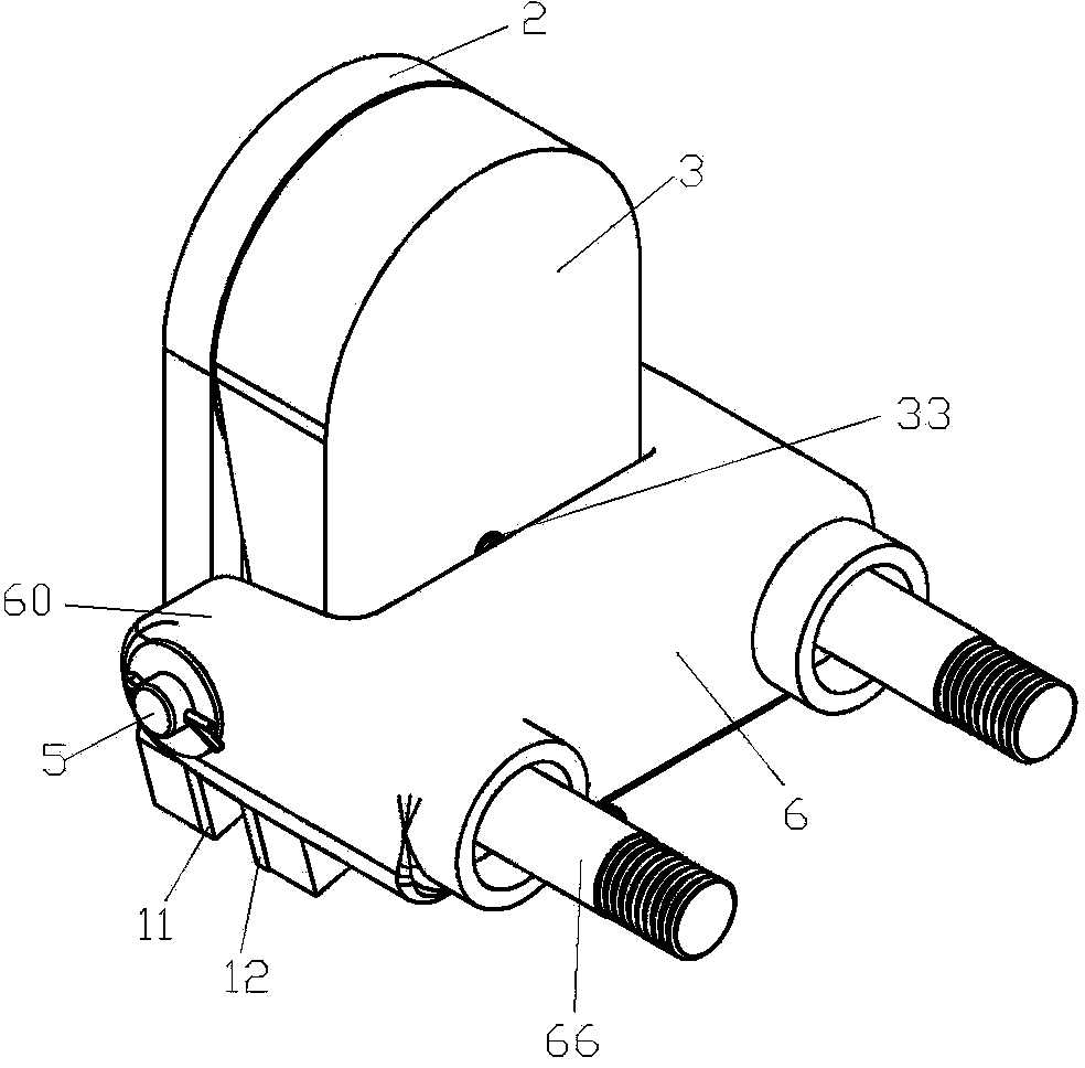
[0017] Example 1, such as figure 1 , 2 , 3, a traction machine brake, including a brake disc 1, the left and right sides of the disc surface of the brake disc 1 are respectively provided with a left brake pad 11 and a right brake pad 12, and the left brake pad 11 faces away from the brake pad. One side of the moving disc 1 is fixed on an armature plate 2, the side of the right brake pad 12 facing away from the brake disc 1 is fixed on an iron core plate 3 facing the armature plate 2, and the side of the armature plate 2 is close to the brake disc 1 The part above the brake disc 1 and the part of the core plate 3 on the side of the brake disc 1 above the brake disc 1 are respectively fixed with connecting parts that can cross along the left and right directions, and the connecting part of the armature plate 2 and the core plate The connecting parts of 3 are intersected to form a combined connecting part 4 and connected in series through connecting shaft rods 5 arranged alo...

Embodiment 2

[0019] Embodiment 2, the difference between it and Embodiment 1 is that: the side of the brake mounting seat 6 near the iron core plate 3 is located above the connection shaft 5, and an adjustment spring 33 for resisting the iron core plate 3 is provided, and the iron core An adjustment screw 30 extending toward the side facing away from the armature plate 2 is fixed on the part of the plate 3 facing away from the armature plate 2 below the connecting shaft 5, and an adjustment screw 30 that cooperates with the adjustment screw 30 is fixed below the brake mounting seat 6. Plate 31, the adjustment plate 31 is provided with a through hole for the adjustment screw rod 30 to pass through, and the adjustment screw rod 30 is equipped with a corresponding adjustment nut.


PUM


Abstract

The invention relates to the technical field of elevator manufacturing, in particular to a traction machine brake. The traction machine brake comprises a brake disc. A left brake pad and a right brake pad are arranged on the two sides of the left surface and the right surface of the brake disc respectively. The side, backing on to the brake disc, of the left brake pad is fixed to an armature plate. The side, backing on to the brake disc, of the right brake pad is fixed to an iron core plate right opposite to the armature plate. A connecting part is fixed to the side, close to the brake disc, of the armature plate and located above the brake disc, a connecting part is fixed to the side, close to the brake disc, of the iron core plate and located above the brake disc, and the two connecting parts can be crossed in the left-and-right direction. The connecting part of the armature plate and the connecting part of the iron core plate form a combined connecting part after being crossed and are connected in series through a connecting shaft rod arranged in the front-and-back direction, and the part, in front of the armature plate and the iron core plate, of the connecting shaft rod and the part, at back of the armature plate and the iron core plate, of the connecting shaft rod are connected to a brake installation base. The part, above the connecting shaft rod, of the iron core plate is provided with an electrified coil and a brake spring used for abutting against the armature plate. The traction machine brake is high in safety and stability, small in loss and low in noise and cost.

Description

technical field [0001] The invention relates to the technical field of elevator manufacturing, in particular to a traction machine brake. Background technique [0002] As the driving part of the elevator, the traction machine is a device that drives the elevator car and the counterweight device to run up and down. It is mainly composed of motors, brakes, traction wheels and other components. The brake is a safety part of the elevator and is to ensure the safe operation of the elevator The basic device of the elevator is an electromechanical friction type normally closed brake. When the elevator is not working, the brake is applied. When the elevator is running, the brake is released. The friction of the brake wheel produces a braking torque; when the elevator is moving, it relies on electromagnetic force to release the brake. The requirements for the elevator brake are: it can generate enough braking torque. When the brake is released or braked, it is required to be stable. ...

Claims


Application Information

Patent Timeline
Patent Type & Authority Applications(China)
IPC IPC(8): B66D5/08B66D5/30
CPCB66D5/14B66D5/30
Inventor 邱伟伟郭娜叶佳芳
Owner GIANT KONE ELEVATOR CO LTD
Why Eureka
Try Eureka