A traction machine brake

A machine brake and brake technology, applied in the direction of the hoisting device, can solve the problems of magnetic steel demagnetization, high processing difficulty, difficult adjustment, etc., and achieve the effects of cost reduction, high operation safety and stability, and structural strength.

Active Publication Date: 2017-01-11
GIANT KONE ELEVATOR CO LTD
View PDF6 Cites 0 Cited by
  • Summary
  • Abstract
  • Description
  • Claims
  • Application Information

AI Technical Summary

Problems solved by technology

[0002] As the driving part of the elevator, the traction machine is a device that drives the elevator car and the counterweight device to run up and down. It is mainly composed of motors, brakes, traction wheels and other components. As the safety component of the elevator, the brake is the basic device to ensure the safe operation of the elevator. - Electric friction type normally closed brake, when the elevator is not working, the brake brakes, when the elevator is running, the brake is released, and when the elevator brakes, it relies on the action of mechanical force to make the friction plate rub against the brake wheel to generate braking torque; When the elevator moves, it relies on electromagnetic force to release the brake. The requirements for the elevator brake are: it can generate enough braking torque. Require; As an elevator safety component, the performance and cost of the brake directly determine the quality and competitiveness of the elevator. In the existing technology, most of the brakes are directly braked on the traction sheave, and the long-term action of the brake is related to The friction of the brake wheel heats up, which leads to the demagnetization of the magnetic steel; there are also some disc brakes that are braked on the brake disc, which are difficult to adjust and difficult to process, and the existing brakes are directly produced by the spring force Acting on the brake wheel, this requires higher performance of the spring, and the electromagnetic force generated by the brake coil also needs to be greater to attract the brake

Method used


Image

  • A traction machine brake
  • A traction machine brake
  • A traction machine brake

Examples


Embodiment 1

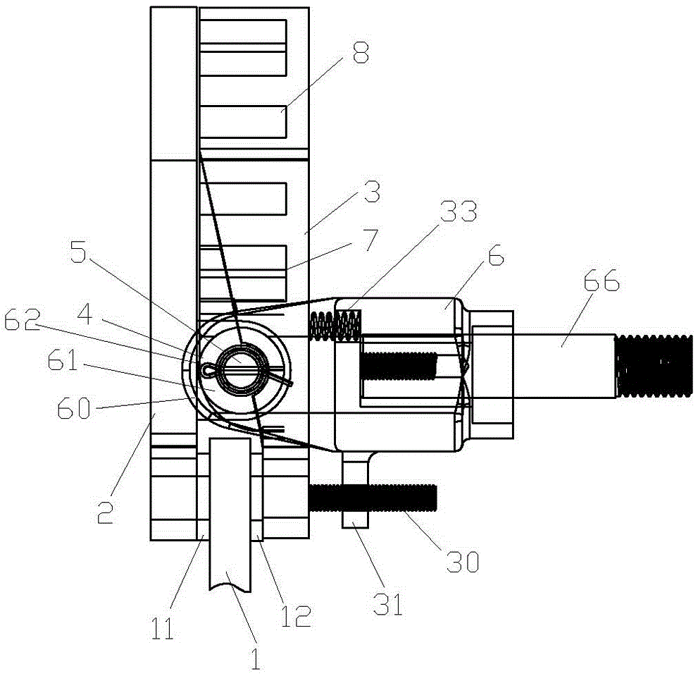
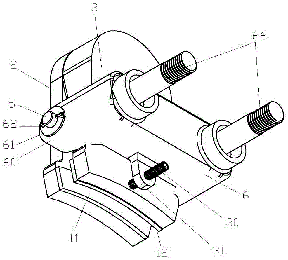
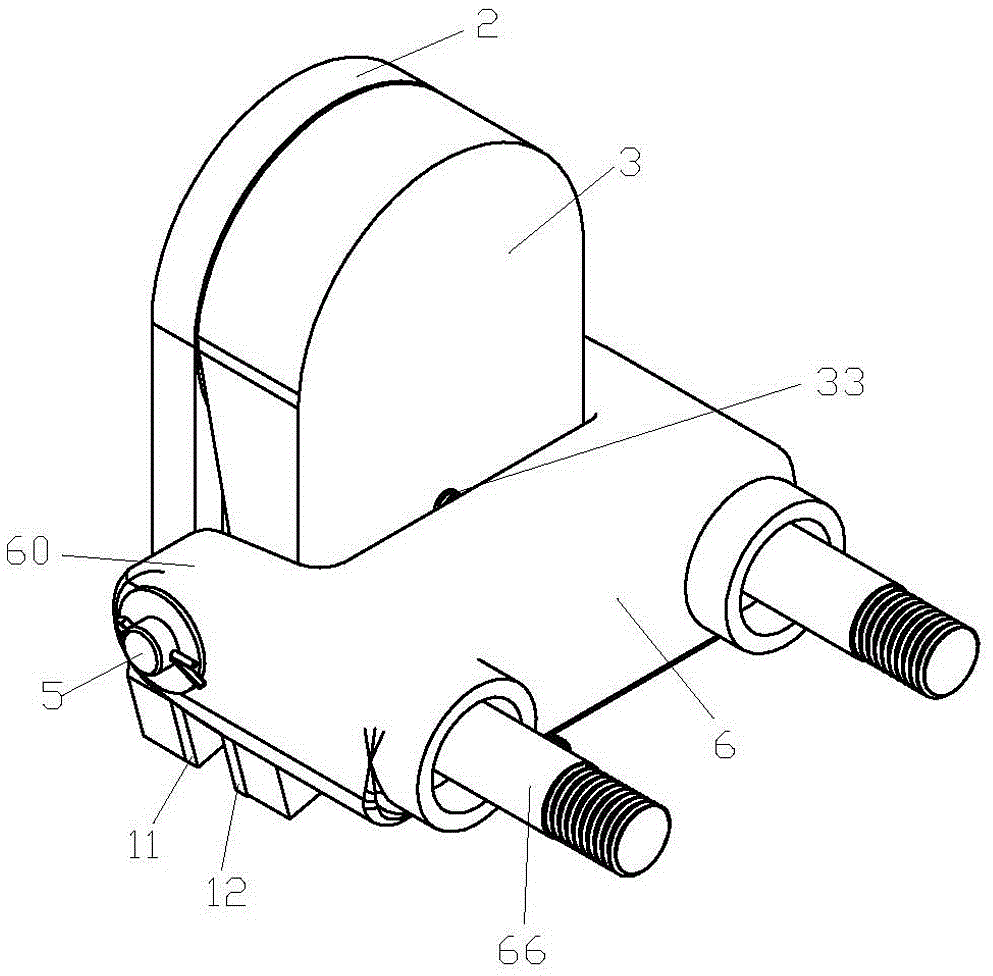
[0017] Example 1 , as shown in the figure 1 、 2 、 3 As shown, a traction machine brake, including a brake disc 1 , brake disc 1 There are left brake pads on both sides of the left and right discs 11 and right brake pad 12 , left brake pad 11 facing away from the brake disc 1 Fixed on one side to an armature plate 2 upper right brake pad 12 back to brake disc 1 One side fixed to the armature plate 2 a core board 3 upper, armature plate 2 by brake disc 1 brake disc on one side 1 Upper part and core plate 3 by brake disc 1 brake disc on one side 1 The upper parts are respectively fixed with connecting parts that can cross along the left and right directions, and the armature plate 2 connection part and core plate 3 The connecting parts of the cross to form a combined connecting part 4 And through the connecting shaft arranged along the front and rear direction 5 connected in series, connecting shafts 5 on t...

Embodiment 2

[0019] Example 2 , which with the example 1 The difference is: brake mount 6 Lean on core plate 3 One side is located on the connecting shaft 5 The upper part is equipped with a core plate for resisting the 3 adjustment spring 33 , core plate 3 Back to armature plate 2 One side is located on the connecting shaft 5 The lower part is fixed with the armature plate facing away from the 2 Adjusting screw extended on one side 30 , brake mount 6 The lower part is fixed with the adjustment screw 30 matching adjustment plate 31 , adjustment board 31 screw for adjustment 30 Through hole through, adjusting screw 30 Equipped with corresponding adjusting nuts.


PUM


Abstract

The invention relates to the technical field of elevator manufacturing, in particular to a traction machine brake. The traction machine brake comprises a brake disc. A left brake pad and a right brake pad are arranged on the two sides of the left surface and the right surface of the brake disc respectively. The side, backing on to the brake disc, of the left brake pad is fixed to an armature plate. The side, backing on to the brake disc, of the right brake pad is fixed to an iron core plate right opposite to the armature plate. A connecting part is fixed to the side, close to the brake disc, of the armature plate and located above the brake disc, a connecting part is fixed to the side, close to the brake disc, of the iron core plate and located above the brake disc, and the two connecting parts can be crossed in the left-and-right direction. The connecting part of the armature plate and the connecting part of the iron core plate form a combined connecting part after being crossed and are connected in series through a connecting shaft rod arranged in the front-and-back direction, and the part, in front of the armature plate and the iron core plate, of the connecting shaft rod and the part, at back of the armature plate and the iron core plate, of the connecting shaft rod are connected to a brake installation base. The part, above the connecting shaft rod, of the iron core plate is provided with an electrified coil and a brake spring used for abutting against the armature plate. The traction machine brake is high in safety and stability, small in loss and low in noise and cost.

Description

technical field [0001] The invention relates to the technical field of elevator manufacturing, in particular to a traction machine brake. Background technique [0002] As the driving part of the elevator, the traction machine is a device that drives the elevator car and the counterweight device to run up and down. It is mainly composed of motors, brakes, traction wheels and other components. As the safety component of the elevator, the brake is the basic device to ensure the safe operation of the elevator. - Electric friction type normally closed brake, when the elevator is not working, the brake brakes, when the elevator is running, the brake is released, and when the elevator brakes, it relies on the action of mechanical force to make the friction plate rub against the brake wheel to generate braking torque; When the elevator moves, it relies on electromagnetic force to release the brake. The requirements for the elevator brake are: it can generate enough braking to...

Claims


Application Information

Patent Timeline
Patent Type & Authority Patents(China)
IPC IPC(8): B66D5/08B66D5/30
CPCB66D5/14B66D5/30
Inventor 邱伟伟郭娜叶佳芳
Owner GIANT KONE ELEVATOR CO LTD
Why Eureka
Try Eureka