
Reluctance motor and rotor thereof

A reluctance motor and rotor technology, applied in the direction of magnetic circuit rotating parts, magnetic circuits, electrical components, etc., can solve the problems of easy demagnetization of permanent magnets, reduce the specific electromagnetic force amplitude, etc., to improve the defects of easy demagnetization, The effect of increasing the reliability of the motor and reducing the electromagnetic force of the motor

Active Publication Date: 2020-08-14
ZHUHAI GREE REFRIGERATION TECH CENT OF ENERGY SAVING & ENVIRONMENTAL PROTECTION
View PDF8 Cites 0 Cited by
  • Summary
  • Abstract
  • Description
  • Claims
  • Application Information

AI Technical Summary

Problems solved by technology

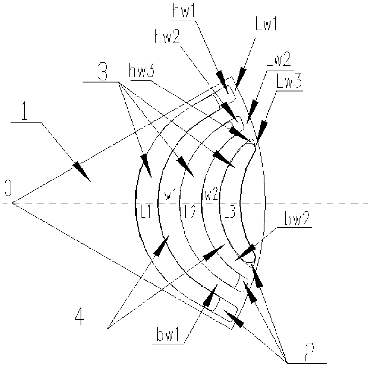
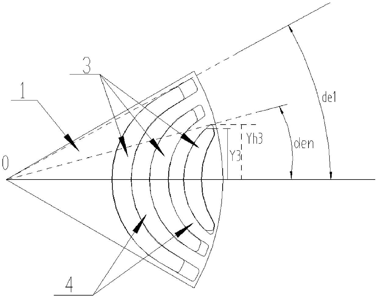
[0005] In view of this, the present invention provides a reluctance motor and its rotor. The present invention can at least solve one of the following technical problems: the problem that permanent magnets are easy to demagnetize can be improved, and the specific electromagnetic force amplitude caused by the inherent characteristics of the motor can be reduced.

Method used


Image

  • Reluctance motor and rotor thereof
  • Reluctance motor and rotor thereof
  • Reluctance motor and rotor thereof

Examples


Embodiment Construction

[0031] Example embodiments will now be described more fully with reference to the accompanying drawings. Example embodiments may, however, be embodied in many forms and should not be construed as limited to the embodiments set forth herein; rather, these embodiments are provided so that this disclosure will be thorough and complete, and will fully convey the concept of example embodiments to those skilled in the art. The same reference numerals denote the same or similar parts in the drawings, and thus their repeated descriptions will be omitted.

[0032] Furthermore, the described features, structures, or characteristics may be combined in any suitable manner in one or more embodiments. In the following description, numerous specific details are provided in order to give a thorough understanding of embodiments of the present disclosure. However, those skilled in the art will appreciate that the technical solutions of the present disclosure may be practiced without one or mo...


PUM


Abstract

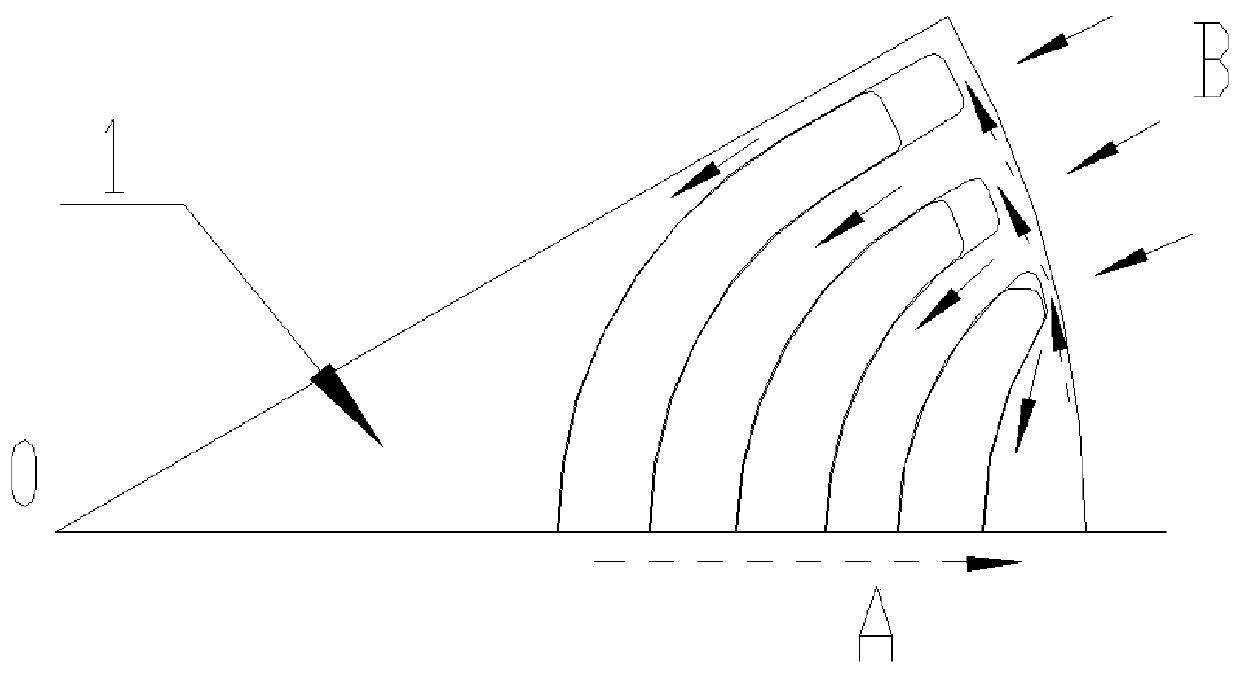
The invention provides a reluctance motor and a rotor thereof. A plurality of sets of magnetic pole structures are formed on the rotor, each set of magnetic pole structure comprises n installation grooves and n permanent magnets, each permanent magnet is installed in the corresponding installation groove, n is a natural number and is larger than or equal to 3, and n-1 magnetic conduction channelswide in the middle and narrow in the two sides are formed between the adjacent installation grooves of the n installation grooves. The defect that demagnetization is extremely easy due to the adoptionof ferrite permanent magnets can be overcome, and the motor reliability is improved. Preferably, through the configuration relationship between the magnetic conduction channel 4 and a magnetic isolation bridge part, the defect that the motor rotor is extremely easy to demagnetize is effectively improved, the reliability of the motor is improved, the electromagnetic force of the motor can be further reduced, electromagnetic vibration caused by overlarge electromagnetic force amplitude is reduced, and electromagnetic noise is reduced.

Description

technical field [0001] The invention belongs to the field of electrical appliances, and in particular relates to a reluctance motor and a rotor thereof. Background technique [0002] The existing two-layer reluctance motor, such as the magnetic barrier permanent magnet assisted synchronous reluctance motor, has the characteristics of high efficiency due to the large use of reluctance torque, but because it uses ferrite permanent magnets with low coercive force, the The problem of irreversible demagnetization of permanent magnets is extremely prone to occur. For example, for this type of motor with 36 slots and 6 poles, due to its own characteristics, the electromagnetic force of 36 times frequency is outstanding, which affects the noise. In the existing synchronous reluctance motor, under the action of a large current, the stator flux linkage flowing through the magnetic conduction path 4 is too large, resulting in saturation of the magnetic circuit, a sharp increase in cur...

Claims


Application Information

Patent Timeline
Patent Type & Authority Applications(China)
IPC IPC(8): H02K1/27
CPCH02K1/27H02K1/274H02K2213/03
Inventor 张辉周博陈华杰朱晓光刘进超
Owner ZHUHAI GREE REFRIGERATION TECH CENT OF ENERGY SAVING & ENVIRONMENTAL PROTECTION
Learn More