

Permanent magnetic force vehicle
A permanent magnet force and permanent magnet plate technology, applied in electric traction, electric vehicles, vehicle parts, etc., can solve the problems of inability to apply rail transit transformation, complex maglev train technology, high operation and maintenance costs, and achieve low construction accuracy requirements and track rails. The material is easy to use, the effect of suspension and strong guiding force
- Summary
- Abstract
- Description
- Claims
- Application Information
AI Technical Summary
Problems solved by technology
Method used
Image

Examples
specific Embodiment approach 1
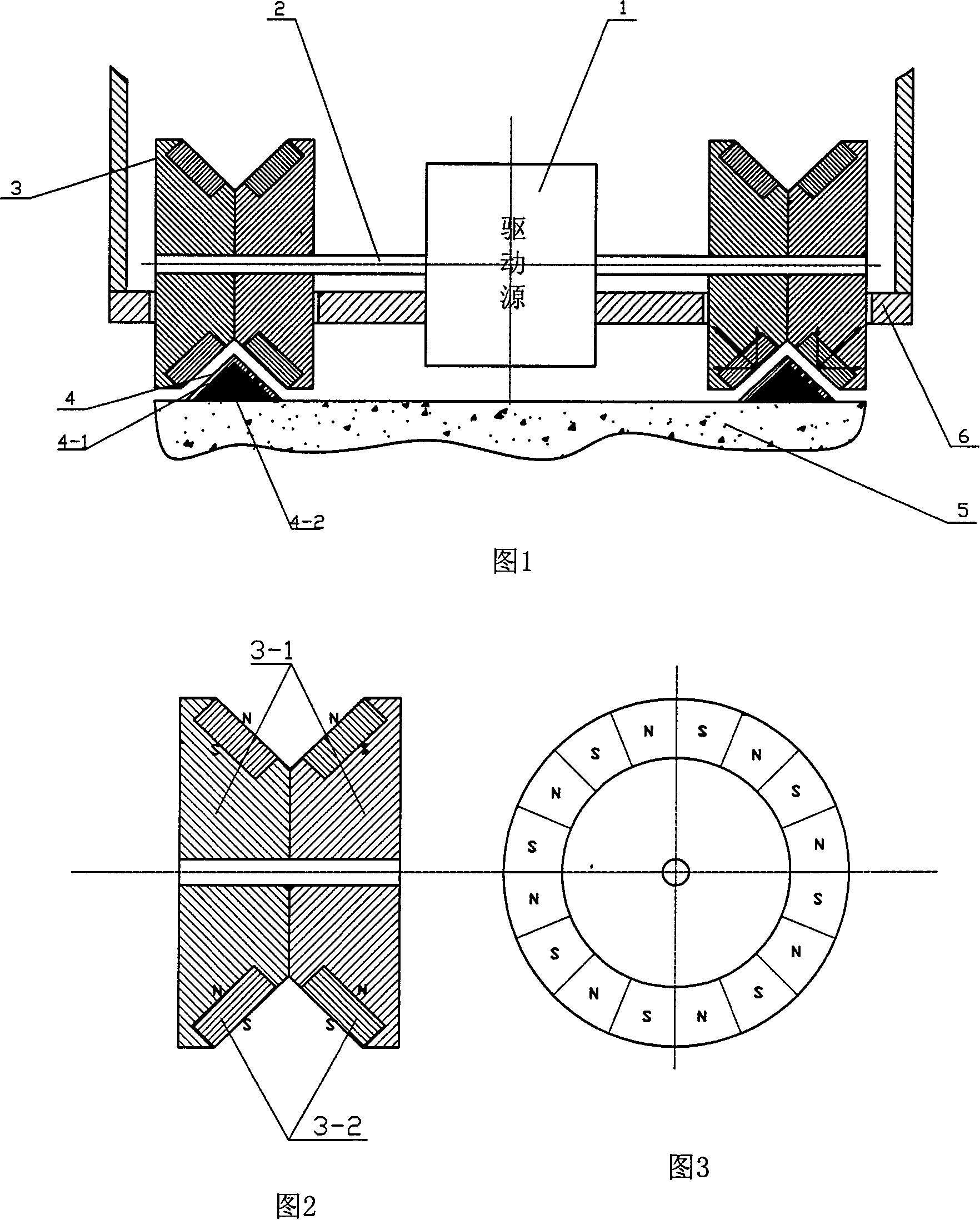
[0047]Specific embodiment one: as shown in Fig. 1, Fig. 2, Fig. 3, drive source is set on the center of symmetry above (or below) of car body base plate 6, and its power output shaft 2 stretches out symmetrically from engine left and right ends, On the protruding shaft, the magnetic wheel 3 is symmetrically fixed left and right; Consists of two identical conical magnetic coils 3-2, each magnetic coil 3-2 is composed of an integral conical permanent magnetic coil along the circumferential partition, and is magnetized alternately with multi-poles along the thickness direction, or consists of several blocks The permanent magnets magnetized along the thickness direction are assembled alternately along the circumferential direction, and the number of partitions or magnetic blocks of the magnetic ring 3-2 is determined according to design calculations. Considering the technology, the magnetic wheel 3 can be made in combination. The track 4 is composed of a track seat 4-2 of non-mag...
specific Embodiment approach 2
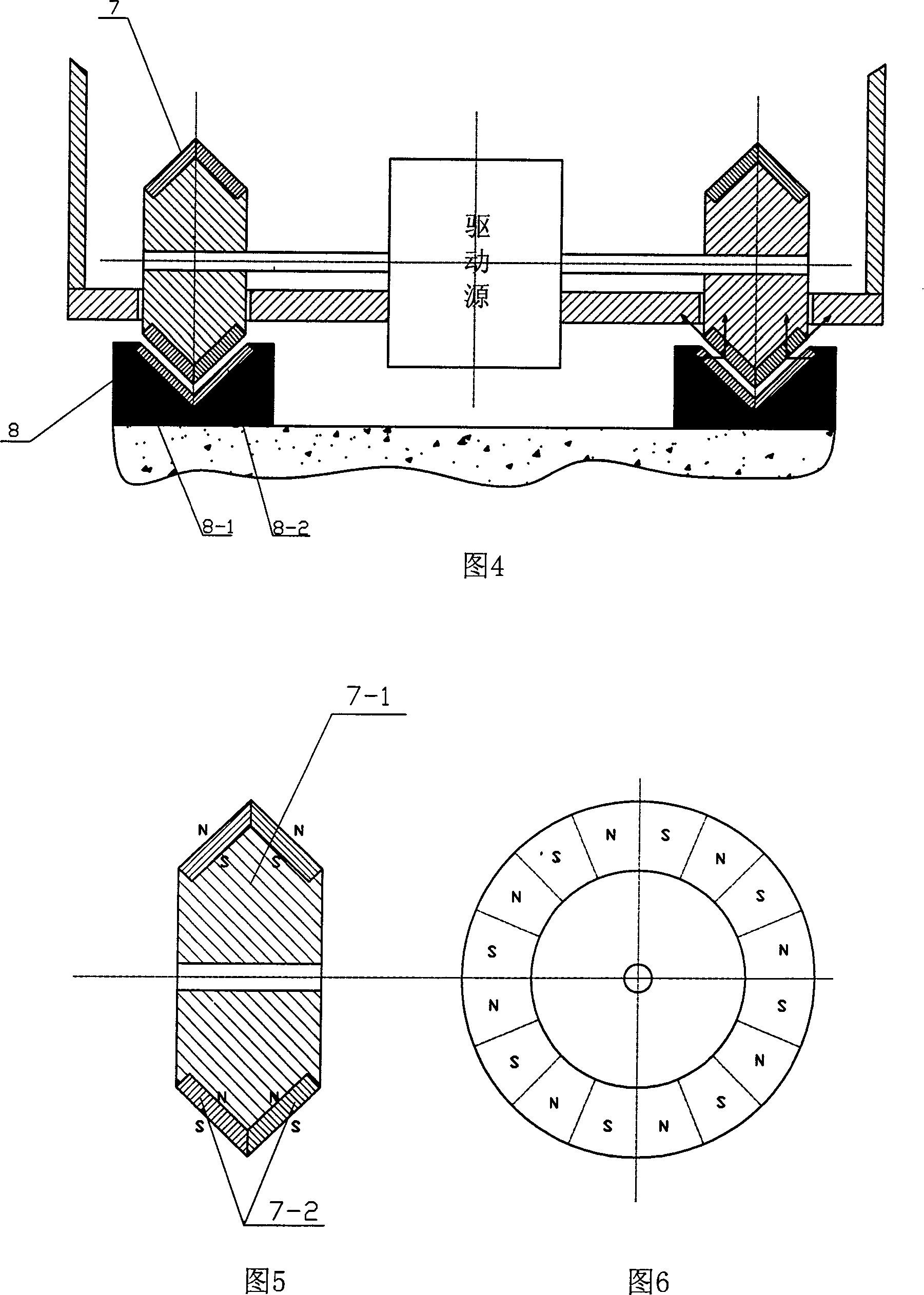
[0050] Embodiment 2: In Embodiment 1, the shapes of the magnetic wheel groove and the track section are interchanged, and other structures remain unchanged. Promptly as shown in Fig. 4, Fig. 5, Fig. 6, non-magnetic track seat 8-1 is made top center to have V-shaped groove, and lining induction plate 8-2 is made in V-shaped groove; Magnetic wheel 7 of magnetic wheel 7 -1 is made into a discus shape, and the permanent magnetic ring 7-2 is fixed on its conical surface ring, and each permanent magnetic ring 7-2 is divided into circumferentially divided sections by an integral conical permanent magnetic ring, and multi-pole polarity along the thickness direction Alternately magnetized, or composed of several permanent magnets magnetized along the thickness direction alternately along the circumferential polarity, the number of partitions or magnetic blocks of the magnetic ring 7-2 is determined according to design calculations. The principles of suspension, guidance and propulsion ...
specific Embodiment approach 3
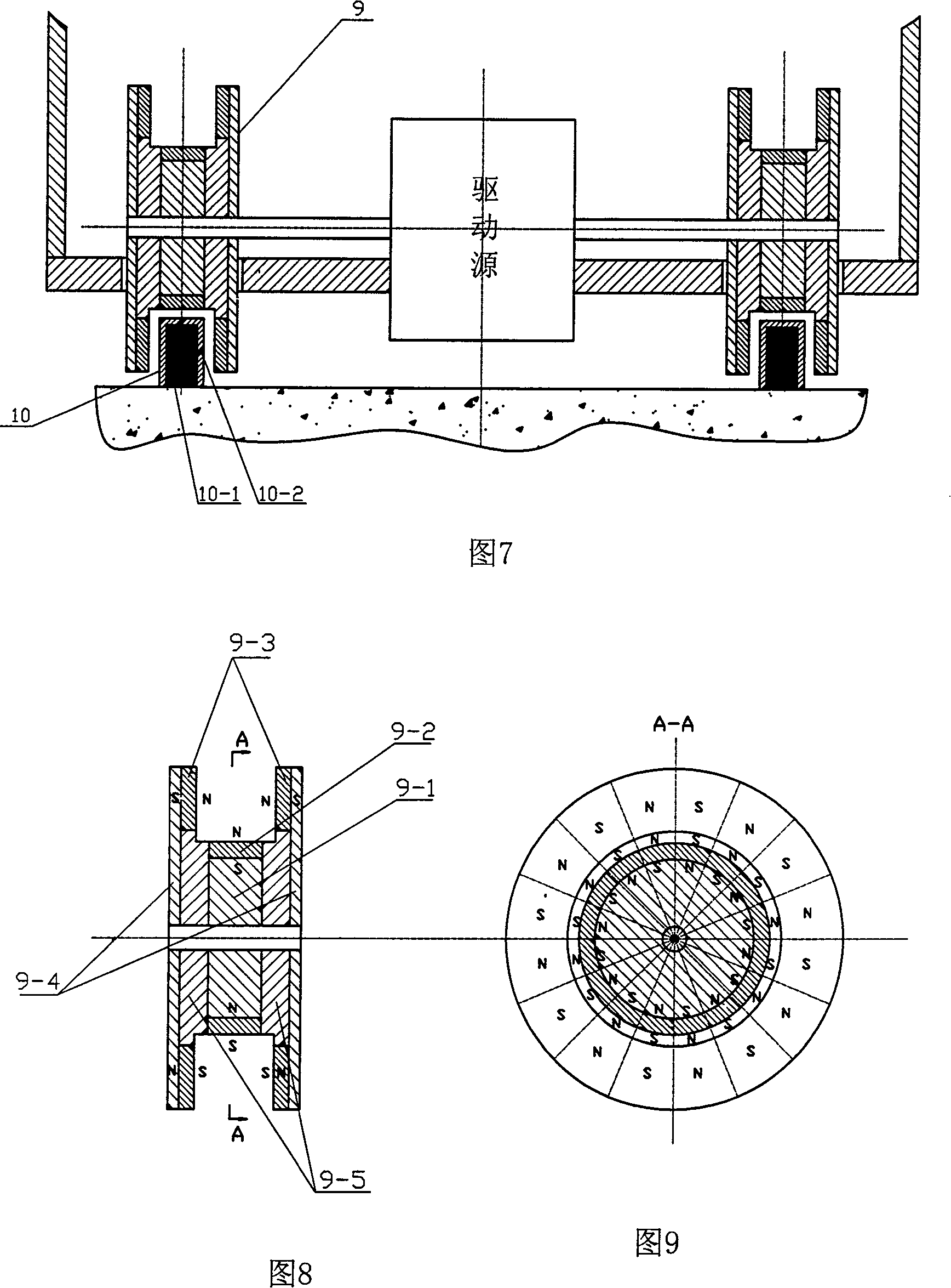
[0051] Embodiment 3: The shapes of the magnetic wheel groove and the track section in Embodiment 1 are changed, and other structures remain unchanged. As shown in Fig. 7, Fig. 8, and Fig. 9, the cross section of the track base 10-1 is made into a rectangle, and the induction plate 10-2 is lined on its top, left side and right side. The magnetic wheel 9 is made into a bobbin shape, leaving a gap to ride on the top of the track 10. The magnetic ring 9-2 on the magnetic wheel 9 and the plane on the track 10 is divided along the circumferential direction by an integral permanent magnetic ring, and multi-pole along the radial direction The polarity is alternately magnetized, or it is composed of several permanent magnets magnetized in the radial direction and the polarity is alternately assembled in the circumferential direction. The number of partitions or magnetic blocks of the magnetic ring 9-2 is determined according to the design calculation; The ring is fixedly sleeved on the...
PUM
 Abstract
Description
Claims
Application Information