Pressure adjusting valve

A technology for pressure regulation and pressure adjustment, applied in the direction of internal combustion piston engines, engine components, liquid fuel feeders, etc., can solve problems such as difficulty in maintaining durability, unstable valve opening posture, and inability to use steel balls, etc., to achieve durability High, to avoid the increase of sliding resistance, the effect of low price

Inactive Publication Date: 2008-06-04
KEIHIN CORP
View PDF1 Cites 12 Cited by
  • Summary
  • Abstract
  • Description
  • Claims
  • Application Information

AI Technical Summary

Problems solved by technology

[0005]However, in the (1) type of valve, the spherical valve core can use an inexpensive and durable steel ball. On the other hand, the spherical valve core The opening posture of the valve is unstable, so there is a defect that the valve closing hysteresis is likely to occur due to the oscillation of the end surface, and in

Method used


Image

  • Pressure adjusting valve
  • Pressure adjusting valve
  • Pressure adjusting valve

Examples


Embodiment Construction

[0034] Next, preferred embodiments of the present invention will be described with reference to the accompanying drawings.

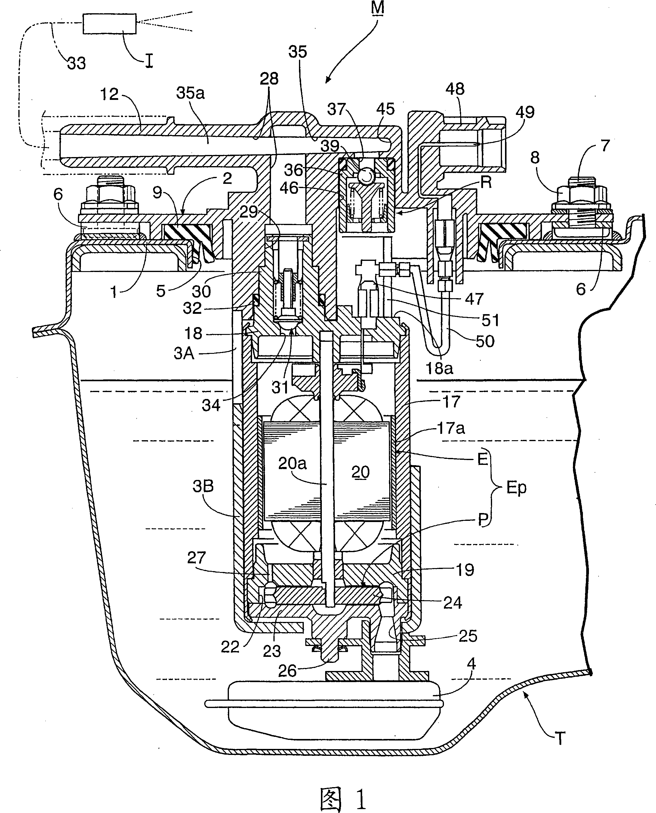
[0035] First, the first embodiment of the present invention will be described. In FIG. 1, a fuel supply module M for supplying fuel in a fuel tank T to a fuel injection valve I of an engine is mounted on a top wall 1 of a fuel tank T mounted on a motorcycle. This fuel supply module M has: an installation base member 2 ; an electric pump Ep arranged vertically in the axial direction directly below the installation base member 2 ; and an upper pump holder 3A integrally formed on the installation base member 2 . the lower pump support 3B, which is detachably engaged with the upper pump support 3A, and accommodates and holds the electric pump Ep in cooperation with the installation base member 2; and the fuel filter installed at the lower end of the electric pump Ep 4.

[0036] An opening 5 for inserting the electric pump Ep into the top wall 1 of the fuel...


PUM


Abstract

The present invention provides pressure-adjusting valve, which comprises: valve sleeve (36), which comprises high-pressure mouth, and the valve chamber (42) linked between the valve seat (38) and the mouth of the high pressure; valve core (39), which move in harmonization with the said valve seat to open and close the high pressure mouth; and voltage-adjusting spring (40), which insert force to the valve core-to-valve close valve direction with a set load. In the pressure-adjusting valve, the said valve core is in sphere-shape, and the valve room comprises the valve maintaining device (41) which has the sphere location concave part (55); part of the said valve core rotate with set in the location valve part; the guiding device (43) of the valve rod (41b) supporting the valve maintaining device is compressed into the inner circle of the valve sleeve and a pressure-adjusting spring is set between the location part and the valve maintaining device. Hence , the valve core can use steel ball, and reduce the flutter of the valve core, and get the pressure adjusting valve with satisfactory durability and high performance and low cost.

Description

technical field [0001] The present invention relates to an improvement of a pressure regulating valve, which comprises: a valve sleeve having a high pressure port receiving a high pressure fluid to be regulated, and a valve chamber connected to the high pressure port via a valve seat and open to the low pressure part ; the valve core, which cooperates with the above-mentioned valve seat accommodated in the above-mentioned valve chamber to open and close the above-mentioned high-pressure port; Apply force in the seating direction. Background technique [0002] The above-mentioned pressure regulating valve is known as disclosed in Patent Document 1 below. [0003] Patent Document 1: Japanese Patent Laid-Open No. 2003-247470 [0004] In the past, the above-mentioned pressure regulating valve has the following two valves: (1) The pressure regulating spring is directly contacted with the spherical valve core rotatably seated on the valve seat, and the pressure regulating spring...

Claims


Application Information

Patent Timeline
IPC IPC(8): F02M37/00F02M37/10
CPCY02T10/123Y02T10/12
Inventor 福田充菊池政彦新井敏弘
Owner KEIHIN CORP
Why Eureka
Try Eureka