Bearing roller chain

A bearing roller chain and bearing roller technology, applied in the field of bearing roller chains, can solve the problems of shortening the life of the chain, accelerating the wear of the roller 22, increasing the traveling resistance, etc., so as to suppress the increase of the traveling resistance and improve the resistance. Abrasion life and effect of preventing entry of foreign matter

Inactive Publication Date: 2008-06-04
TSUBAKIMOTO CHAIN CO
View PDF1 Cites 8 Cited by
  • Summary
  • Abstract
  • Description
  • Claims
  • Application Information

AI Technical Summary

Problems solved by technology

[0005] The above-mentioned conventional bearing roller chain has insufficient sealing performance because the sealing mechanism is a single seal structure composed of the thrust ring 27 arranged between the roller 22 and the inner link plate 25, so if the thrust ring 27 and the roller If the adhesion of the roller 22 or the inner link plate 25 is low, the lubricating oil may leak to the outside from the gap between the end surface of the roller 22 and the thrust ring 27. In addition, there is a problem that foreign matter such as dust and water enters. This gap is mixed into the lubricating oil, which accelerates the wear of the rollers 22, sleeves 23, rollers 24, etc., and the wear causes poor rotation of the rollers and shortens the life of the chain.
In this case, if the adhesion is improved so that no gap is generated between the thrust ring 27 and the roller 22 or the inner link plate 25, there is a problem that the running resistance of the chain increases and the required power increases.

Method used


Image

  • Bearing roller chain
  • Bearing roller chain
  • Bearing roller chain

Examples


Embodiment Construction

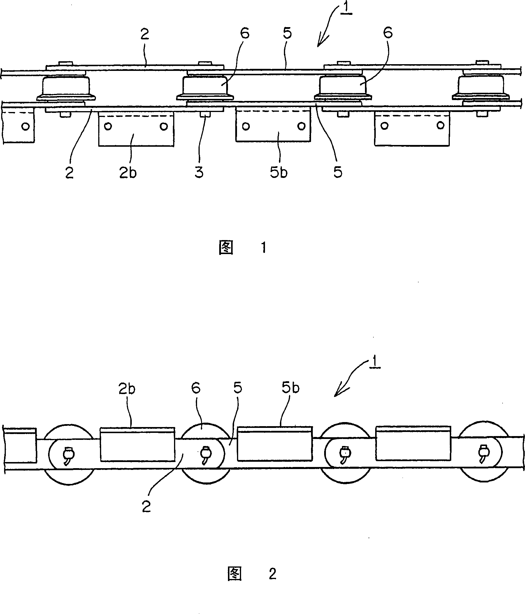
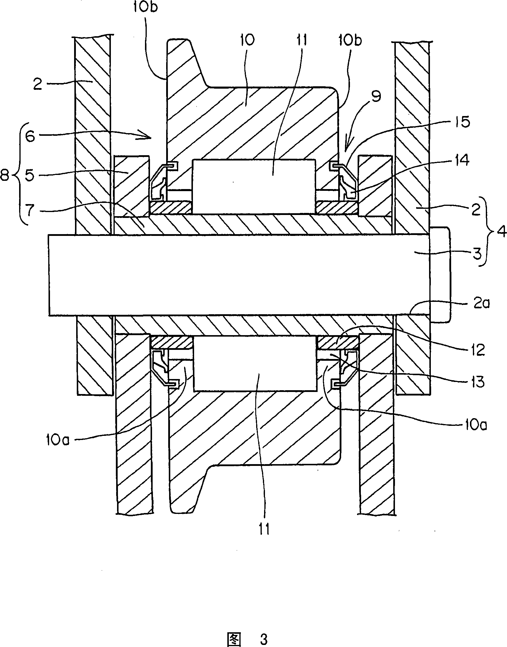
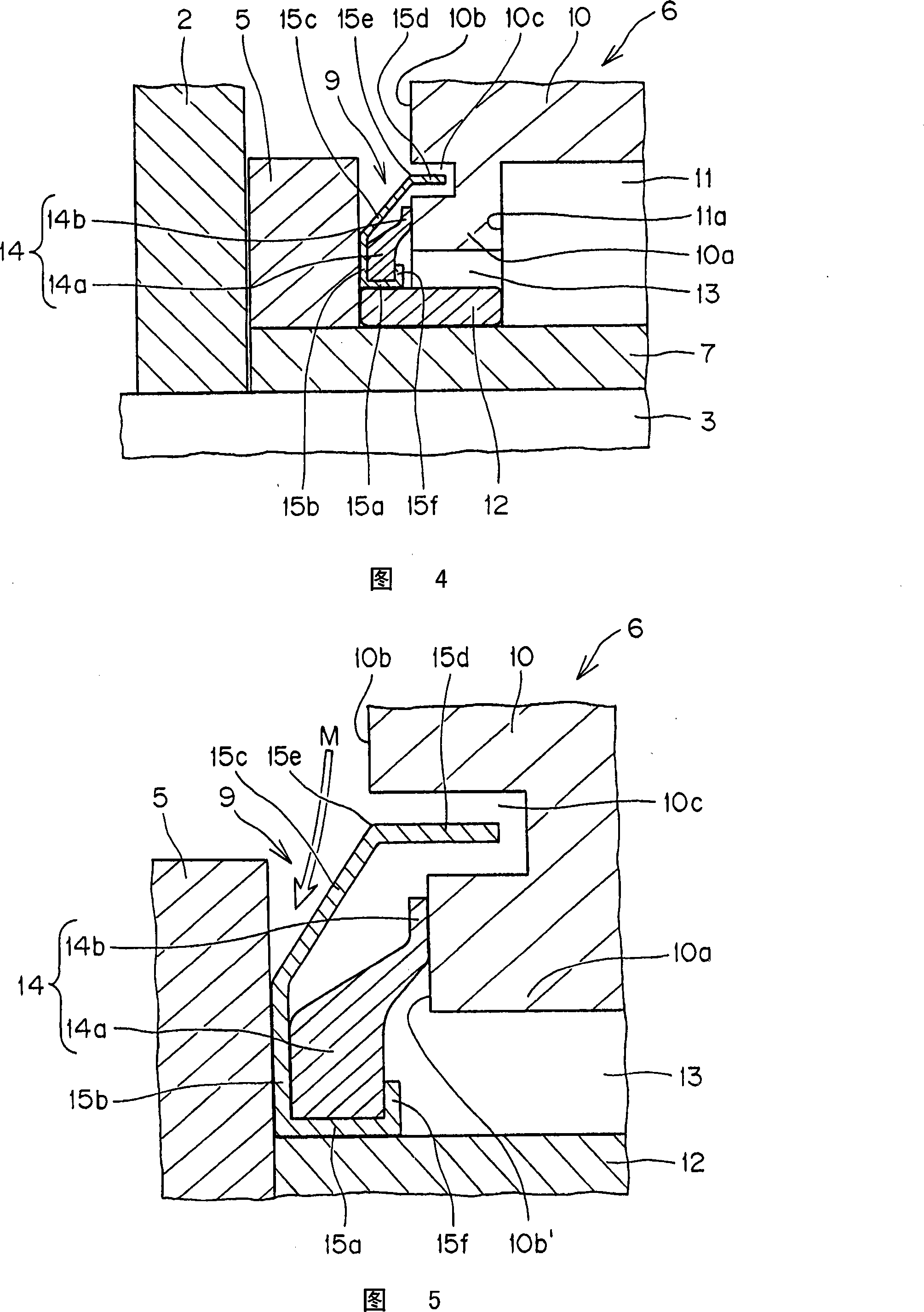
[0053] Embodiments of the present invention will be described with reference to FIGS. 1 to 5 . Fig. 1 is a partial top view of the bearing roller chain, Fig. 2 is a partial side view of the bearing roller chain, Fig. 3 is a sectional view of the bearing roller chain, Fig. 4 is an enlarged sectional view of the main part of the sealing mechanism, and Fig. 5 is a bearing roller An enlarged cross-sectional view of main parts of a sealing mechanism of a modified example of a chain.

[0054] Bearing roller chain 1 is shown in Fig. 1, 2, the outer chain link 4 that is fixed in the pin hole 2a of a pair of outer link plate 2, 2 with the two ends of connecting pin 3 embedded, and will be installed with bearing. Both ends of the sleeve 7 of the roller 6 are fitted and fixed in the sleeve holes 5 a of the pair of inner link plates 5 and 5 , and the inner link 8 is annularly connected by loosely fitting the coupling pin 3 in the sleeve 7 . , as shown in FIG. 3 , a sealing mechanism 9 is...


PUM


Abstract

A bearing roller chain having a seal mechanism preventing entry of foreign substance from the outside, and leaking of lubricating oil leakage to the outside and the like, thereby improving wear resistance of the bearing roller and reducing both the likelihood of rotation failure and the traveling resistance of the chain. The seal mechanism is provided between an inner link plate of the chain and the hollow bearing roller, which has a plurality of internal anti-friction rollers rotatable between the hollow bearing roller and a bush mounted between opposed inner link plates. The seal mechanism encloses the internal anti-friction rollers and comprises two parts, i.e a seal ring having an annular lip portion, which comes into close contact with an outer side surface of the bearing roller and an annular metallic seal member. The metallic seal member forms a labyrinth structure by providing a flange on an outer circumferential portion which loosely enters an annular concave groove in the outer side surface of the bearing roller. The seal mechanism provides a double sealing effect by virtue of the seal ring and the annular metallic seal member.

Description

technical field [0001] The present invention relates to bearing roller chains used in power transmission chains, conveyor chains, and the like, and more particularly to bearing roller chains that are formed by placing seal rings and rings between the bearing rollers and inner link plates. The double-seal structure sealing mechanism composed of shaped metal sealing parts can prevent foreign matter such as dust and water from entering the inside of the bearing rollers in various environments such as dusty atmospheres and watery atmospheres, thereby improving the wear resistance of the bearing rollers. Consumes life. Background technique [0002] Bearing roller chains are widely used as high-speed transmission chains and conveyor chains because they comply with the high-speed and high-load transmission of power. Between the bushing and to prevent the scattering of lubricating oil (grease, oil) sealed between the bearing roller and the bushing, a sealing mechanism is provided b...

Claims


Application Information

Patent Timeline
Patent Type & Authority Applications(China)
IPC IPC(8): F16G13/06B65G19/00
CPCF16G13/06B65G39/09F16J15/002F16C33/7889F16C33/805F16J15/164B65G39/20F16C19/26
Inventor 藤原诚谷村诚今元哲雄
Owner TSUBAKIMOTO CHAIN CO
Why Eureka
Try Eureka