
Method and apparatus for controlling internal combustion engine

A control method and internal combustion engine technology, applied in the direction of engine control, fuel injection control, internal combustion piston engine, etc., can solve the problems of reduced adjustment quality, impossible adjustment of theoretical value, etc.

Active Publication Date: 2013-10-30
ROBERT BOSCH GMBH
View PDF2 Cites 0 Cited by
  • Summary
  • Abstract
  • Description
  • Claims
  • Application Information

AI Technical Summary

Problems solved by technology

The problem with this system is that several setpoint values ​​have to be adjusted simultaneously, that is, several required actual values ​​have to be compensated
This reduces the adjustment quality and in the worst case makes it impossible to adjust the theoretical value

Method used


Image

  • Method and apparatus for controlling internal combustion engine
  • Method and apparatus for controlling internal combustion engine

Examples


Embodiment Construction

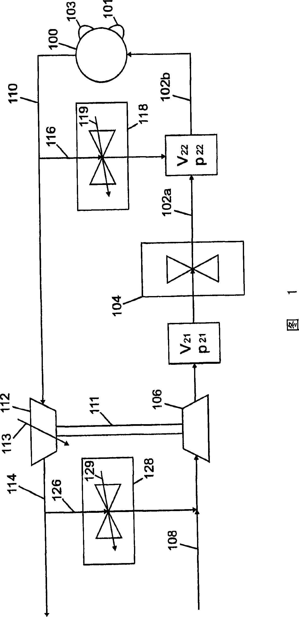
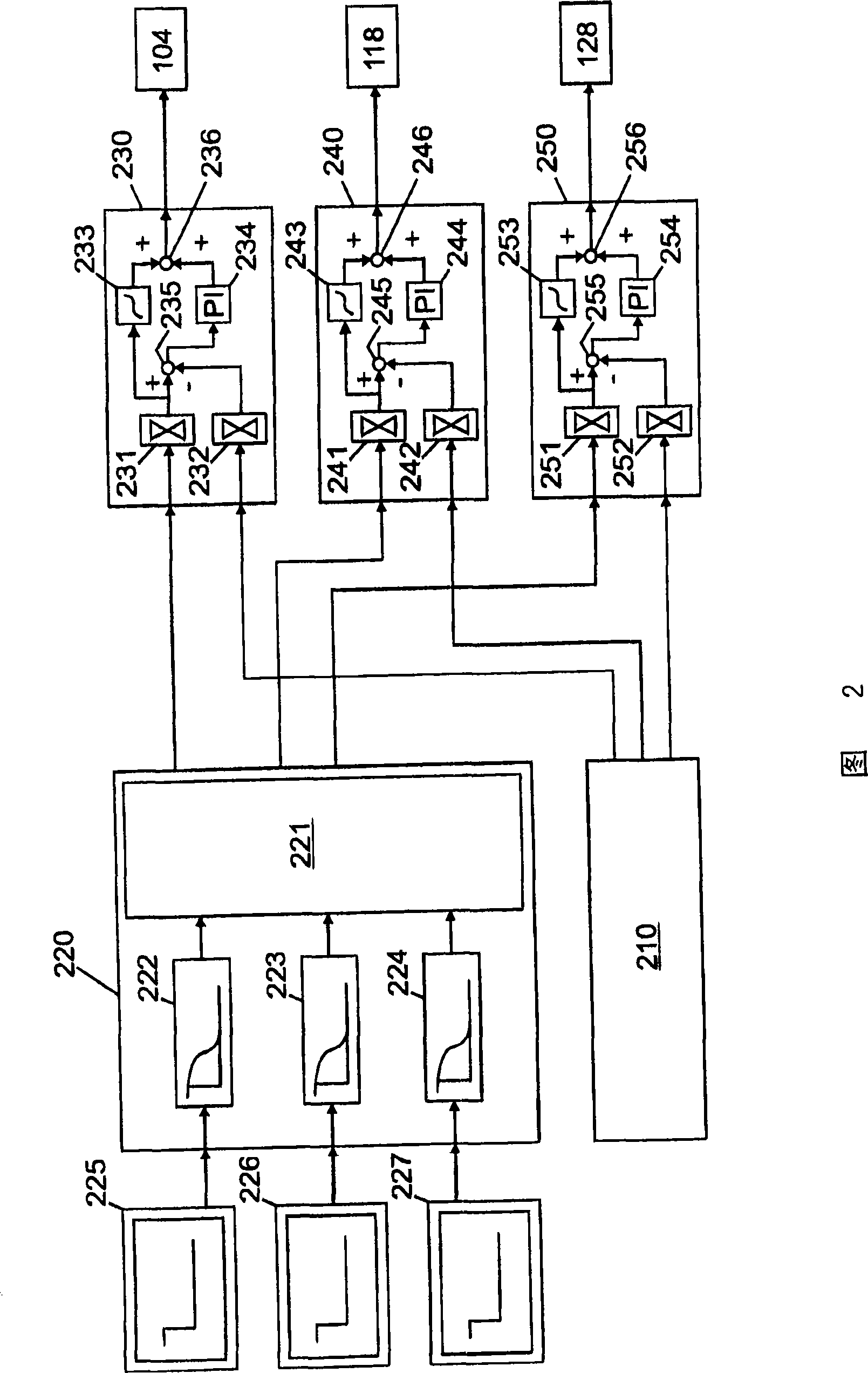
[0013] The method of the present invention will be described below by taking a throttle valve, an exhaust gas recirculation valve on the high-pressure side and an exhaust gas recirculation valve on the low-pressure side as examples. In principle, the inventive approach can be used for all regulators intended to influence a certain gas mass flow, for example fresh air mass flow, exhaust gas mass flow on the high-pressure side or exhaust gas mass flow on the low-pressure side. Obviously, in addition to the fresh air mass flow or the exhaust gas mass flow on the high-pressure side and on the low-pressure side, other parameters corresponding to these parameters can also be adjusted and / or controlled. The actual and theoretical values ​​of these parameters to be mentioned below are therefore the control parameters characterizing the fresh air mass flow, the EGR mass flow on the high-pressure side and the EGR mass flow on the low-pressure side. By control parameter is meant the appr...


PUM


Abstract

A method and apparatus for controlling an internal combustion engine having a first actuator for influencing the gas air mass flow delivered to the internal combustion engine, having a second actuator for influencing the high-pressure-side recirculated exhaust gas mass flow, and having at least one third actuator for influencing the low-pressure-side recirculated exhaust gas mass flow, a first actuating variable for the first actuator being predefinable based on a comparison between a first setpoint and a first actual value for the fresh air mass flow and / or on further modeled or measured variables, a second actuating variable for the second actuator being predefinable based on a comparison between a second setpoint and a second actual value for the high-pressure-side exhaust gas mass flow and / or on further modeled or measured variables, and at least one third actuating variable for the at least one third actuator being predefinable based on a comparison between a third setpoint and a third actual value for the low-pressure-side exhaust gas mass flow and / or on further modeled or measured variables.

Description

technical field [0001] The invention relates to a control method and device for an internal combustion engine. Background technique [0002] A control method and a device for an internal combustion engine are known, for example, from DE 19620036 A1. There, the first controller is used to influence the fresh air mass flow to the internal combustion engine, and the second controller is used to influence the exhaust gas recirculation mass flow. A throttle valve is preferably used as the first regulator, which is arranged downstream of the compressor in the intake manifold. A high-pressure side exhaust gas recirculation valve, which is arranged in the high-pressure side exhaust gas recirculation line, is preferably used as the second regulator. Both the exhaust gas recirculation valve and the throttle valve are adjustable in operation so that in certain operating states the fresh air mass flow and the fraction of the recirculated exhaust gas can be precisely adjusted. General...

Claims


Application Information

Patent Timeline
Patent Type & Authority Patents(China)
IPC IPC(8): F02D41/00F02M25/07
CPCF02M25/0744F02D41/187F02D41/0072F02D41/0007F02D41/1401Y02T10/47Y02T10/144F02D2041/1418F02M25/0754F02M25/0707F02D2041/1409F02M25/0709F02D2200/0402F02M25/0713F02D2041/141F02D2041/1434F02M26/05F02M26/06F02M26/10F02M26/38F02M26/47Y02T10/12Y02T10/40
Inventor T·布莱勒C·斯蒂勒F·海伯
Owner ROBERT BOSCH GMBH
Learn More