Coal gas anhydrous dust collecting equipment of revolving furnace and technique thereof
What is AI technical title?
AI technical title is built by PatSnap AI team. It summarizes the technical point description of the patent document.
A converter gas and process method technology, applied in the direction of gas dust removal, chemical industry, climate sustainability, etc., can solve the problems of increased power of the main induced draft fan, loss of water vapor content, increase, etc., to improve the utilization rate of calorific value , the effect of reducing energy consumption
Active Publication Date: 2010-10-13
北京中冶设备研究设计总院有限公司
View PDF4 Cites 1 Cited by
Summary
Abstract
Description
Claims
Application Information
AI Technical Summary
This helps you quickly interpret patents by identifying the three key elements:
Problems solved by technology
Method used
Benefits of technology
Problems solved by technology
However, the disadvantages of the OG wet-type converter gas dust removal and recovery system are: due to the use of water cooling to cool down, a large amount of heat energy in the gas is lost and the calorific value of the gas is reduced. Under the same conditions, increasing the power of the main induced draft fan increases the Reduce energy consumption and require a huge water supply system and sewage and sludge treatment systems
However, in the currently used dry-process converter gas dedusting process equipment system, the high-temperature gas coming out of the converter vaporization cooling flue is cooled in the evaporative cooling tower by spraying water, which will cause a large amount of heat energy in the gas to be lost and cause The water vapor content in the gas increases, which reduces the calorific value and use value of the gas; under the same conditions, the power of the main induced draft fan is also increased, which increases energy consumption
Method used
Image
Click on the blue label to locate the original text in one second.
Reading with bidirectional positioning of images and text.
Examples
Embodiment
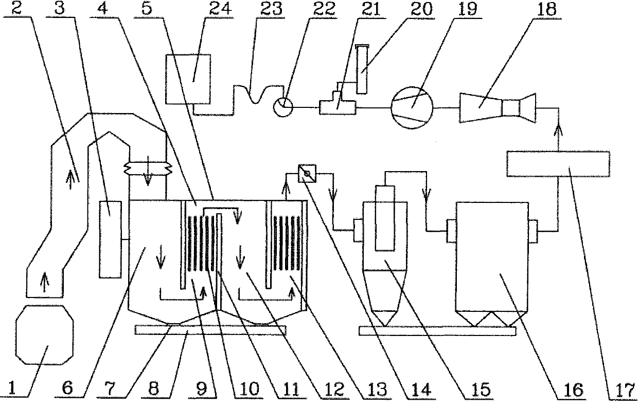
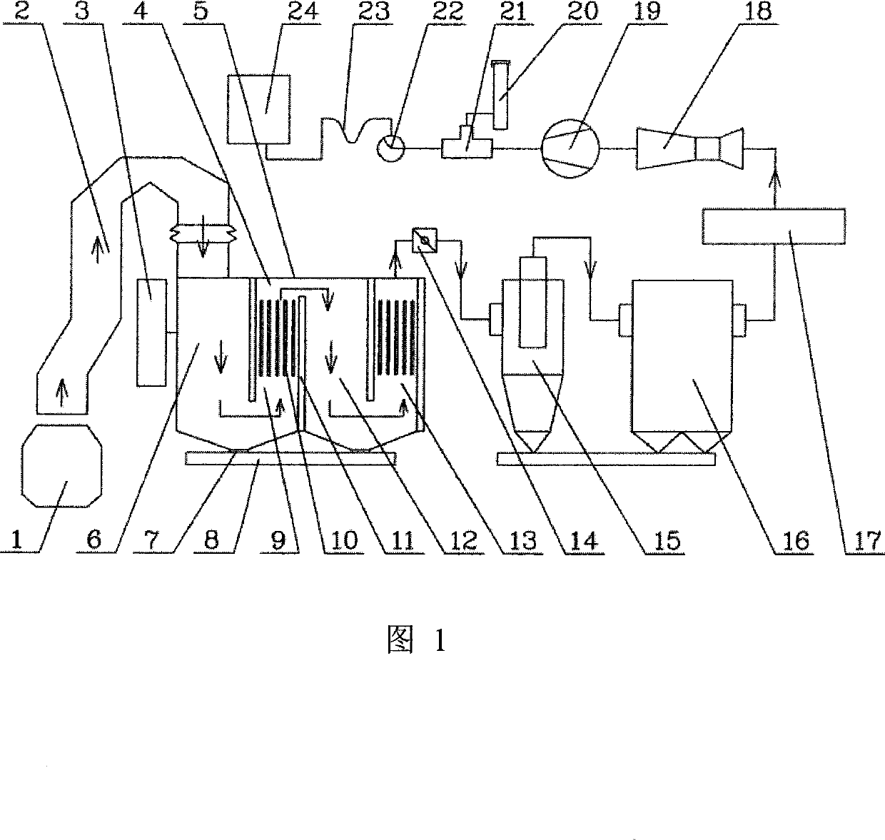
[0010] figure 1 It is a schematic diagram of the mechanism in the embodiment of a converter gas anhydrous dedusting equipment and process method of the present invention, as figure 1 As shown, the method of this embodiment of the invention is as follows: the high-temperature gas generated by the converter 1 passes through the radiant waste heat boiler 2 and transfers part of the heat to the indirect cooling water to generate steam for recovery. After the heat exchange, the temperature of the gas is reduced to 900-1000°C Then enter the convection waste heat boiler 4. In the settling chambers 6 and 12 of the convection waste heat boiler 4, the gas undergoes two gravity settlements, and passes through two convection heat exchange components in the convection heat exchange chambers 9 and 13 to generate steam to recover waste heat. After reducing the temperature of the gas to 250-300°C, the gas enters the regulating valve 14 used to adjust the differential pressure at the furnace m...
PUM
Abstract
The invention relates to a converter coal gas non-water dust removing equipment, which comprises a converter, a radiant type waste-heat boiler, an adjusting valve, a cyclone dust remover, a bag-type dust remover, a coal gas temperature controlling device, a flow meter, a main induced draft fan, a three-way valve, an emission chimney, a rotary water seal, a U-shaped water seal, and a coal gas tank. The invention is characterized in that a convection type waste-heat boiler is connected between the outlet position of the radiant type waste-heat boiler and the adjusting valve, and the convection type waste-heat boiler is composed of a settling chamber, a heat exchange component, a baffle plate, a box body, and an ash discharging opening. A process method comprises the steps that converter coal gas comes into the convection type waste-heat boiler via radiant type waste-heat boiler after recovery waste heat, the gravitational settling is performed to come into the adjusting valve, and the bag-type dust remover, etc to perform dust fining removal after the recovery waste heat, the emission is performed through the three-way valve or the converter coal gas comes into the coal gas tank to perform coal gas recovery, and the invention has the advantage that the energy consumption is reduced through recovering heat energy.
Description
Technical field: [0001] The invention relates to the technical field of steelmaking auxiliary equipment and its technology, in particular to a converter gas anhydrous dedusting equipment and its technology. Background technique: [0002] There are mainly two types of existing converter gas dedusting equipment and its process methods. One is the wet converter gas dedusting recovery system represented by the Japanese OG method. The main process includes the traditional "one article + two articles" system, spray tower +Downward annular venturi system, spray tower+upward annular venturi system, its main structure has experienced adjustable throat type (P-A), movable reversible type (RD), annular seam weight type (RSW) and other replacements, its main equipment consists of Venturi tube, cooling tower, circular seam Venturi tube, dehydrator, water mist separator, flow meter, induced draft fan, three-way valve, water treatment facilities, gas cabinet, water Seal etc. composition. ...
Claims
Application Information
Patent Timeline
Application Date:The date an application was filed.
Publication Date:The date a patent or application was officially published.
First Publication Date:The earliest publication date of a patent with the same application number.
Issue Date:Publication date of the patent grant document.
PCT Entry Date:The Entry date of PCT National Phase.
Estimated Expiry Date:The statutory expiry date of a patent right according to the Patent Law, and it is the longest term of protection that the patent right can achieve without the termination of the patent right due to other reasons(Term extension factor has been taken into account ).
Invalid Date:Actual expiry date is based on effective date or publication date of legal transaction data of invalid patent.

