Eureka AIR delivers breakthrough ideas for toughest innovation challenges, trusted by R&D personnel around the world.

Cast-in-situ concrete hollow slab

A technology of hollow slab and cast-in-place concrete, which is applied in the direction of floors, building components, buildings, etc., and can solve the problems of inconvenient assembly line production, high construction cost and low production efficiency of cast-in-place concrete hollow slabs

Inactive Publication Date: 2008-06-11
湖南邱则有专利战略策划有限公司
View PDF1 Cites 0 Cited by
  • Summary
  • Abstract
  • Description
  • Claims
  • Application Information

AI Technical Summary

Problems solved by technology

However, when the formwork components in this floor slab are produced, it is inconvenient to make, the production efficiency is low, it is not convenient for assembly line production, the production cost is high, and the construction cost of the corresponding cast-in-place concrete hollow slab is high. Therefore, a new type of in-situ concrete is developed. Concrete hollow slabs are urgently needed

Method used


Image

  • Cast-in-situ concrete hollow slab
  • Cast-in-situ concrete hollow slab
  • Cast-in-situ concrete hollow slab

Examples


Embodiment Construction

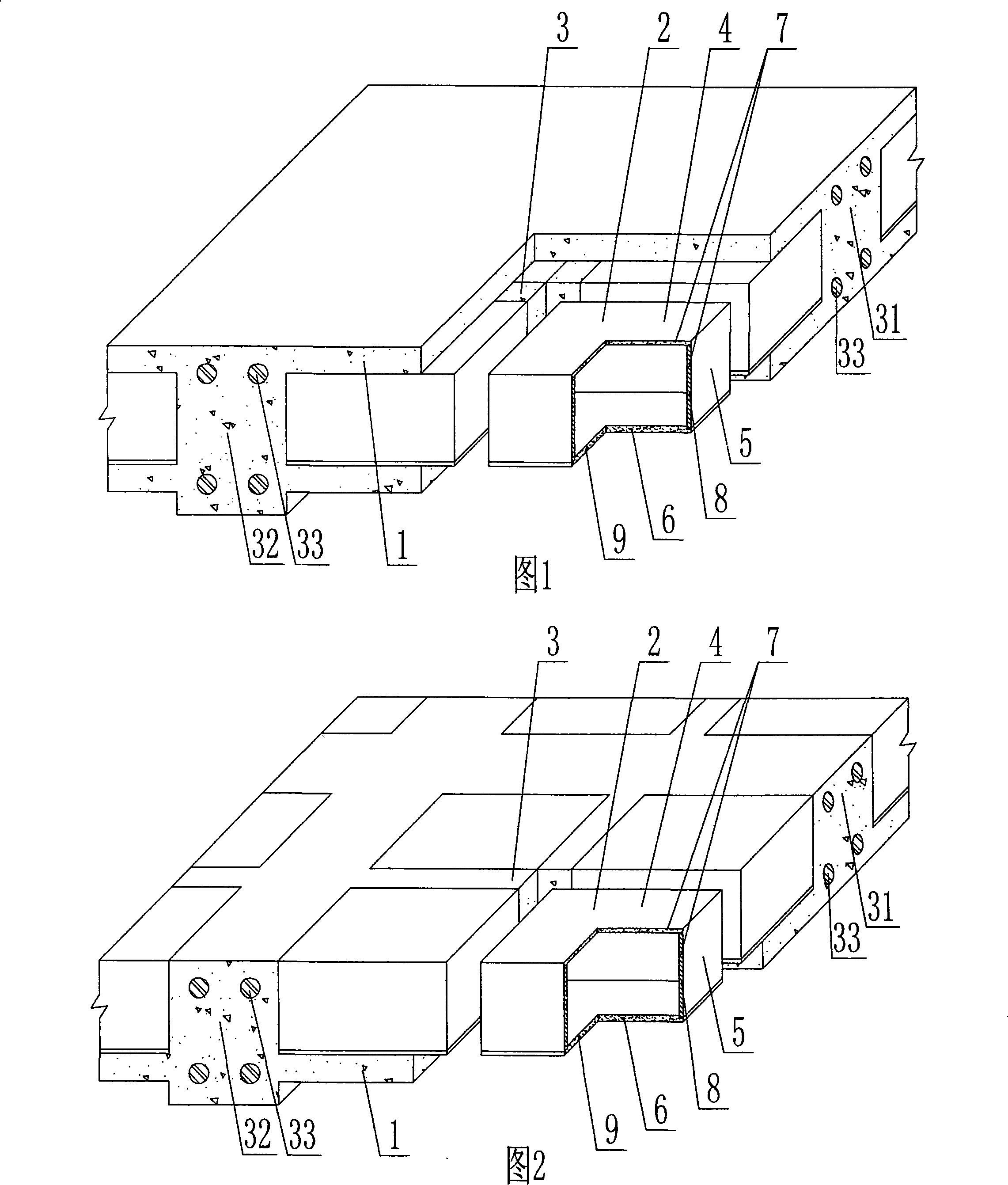
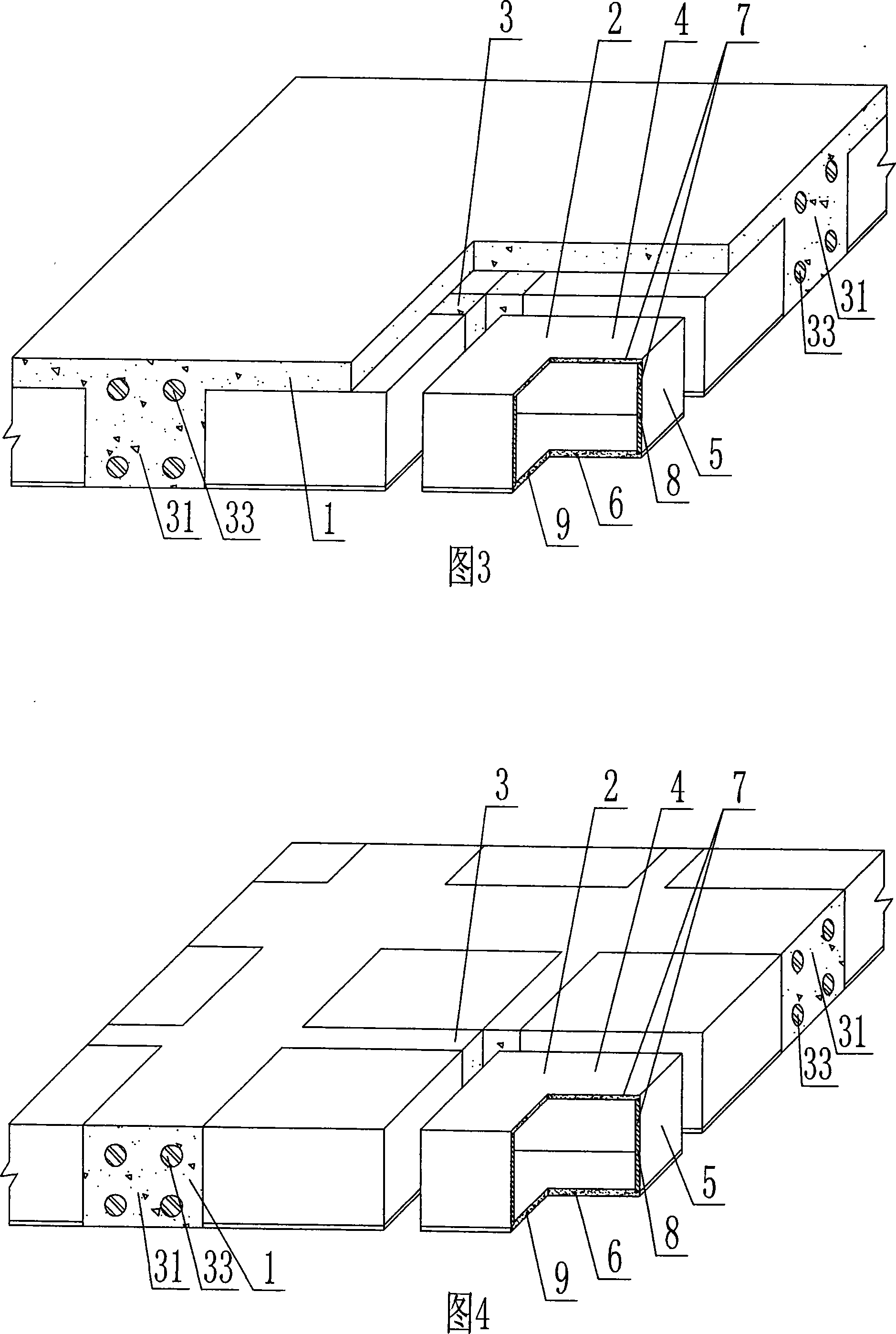
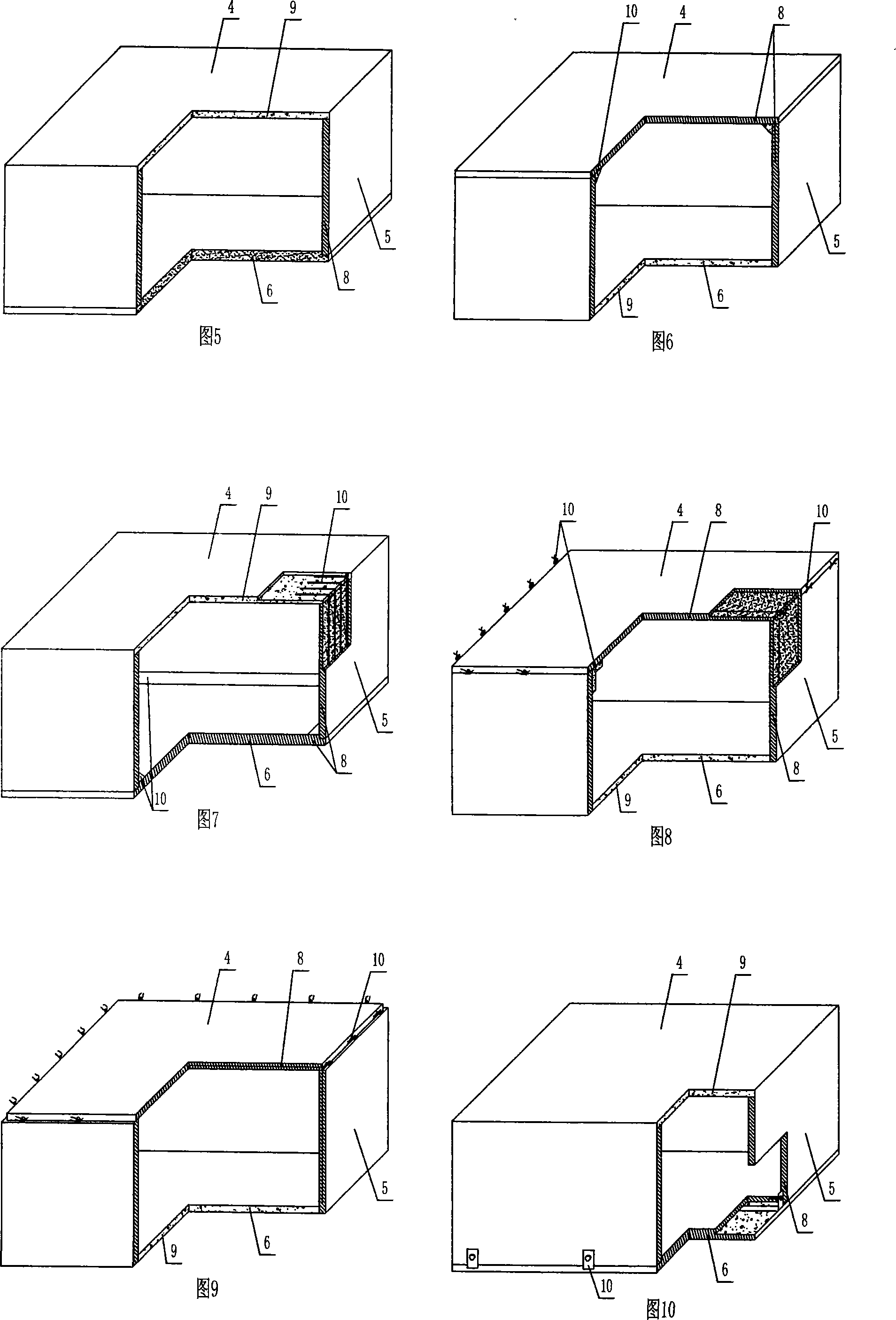
[0082] The present invention will be further described below in conjunction with the accompanying drawings and embodiments.

[0083]As shown in the accompanying drawings, the present invention includes reinforced concrete 1 and cavity formwork components 2, the cavity formwork components 2 are wrapped in the reinforced concrete 1, and the cavity formwork components 2 are cast-in-place reinforced concrete ribs 3 The cavity formwork member 2 includes an upper plate 4, surrounding side walls 5, and a lower plate 6, and the upper plate 4, the surrounding side walls 5, and the lower plate 6 form a closed cavity formwork member, which is characterized in that the closed cavity The upper plate 4, the surrounding side walls 5, and the lower plate 6 of the cavity formwork member 2 are composed of a component 7, and the component 7 is composed of at least one prefabricated plate 8 and at least one cast-in-place plate 9 bonded to the prefabricated plate 8. The upper surface of the plate ...


PUM


Abstract

The invention relates to a cast-in-situ concrete hollow floor slab, which comprises reinforced concrete (1) and cavity die casing components (2), the cavity die casing components (2) are included in the reinforced concrete (1), cast-in-situ reinforced concrete ribs (3) are adopted between the cavity die casing components (2), the invention is characterized in that the upper plates (4), the peripheral side walls (5) and the lower plates (6) of the cavity die casing components (2) are composed of components (7), each component (7) is composed of at least a prefabricated plate (8) and at least a cast-in-situ plate (9) of the bond prefabricated plate (8), the upper surfaces of the upper plates (4) are flushed with the upper surface of the cast-in-situ concrete hollow floor slab or the lower surfaces of the lower plates (6) are flushed with the lower surface of the cast-in-situ concrete hollow floor slab or the upper surfaces of the upper plates (4) and the lower surfaces of the lower plates (6) are flushed with the upper surface and the lower surface of the cast-in-situ concrete hollow floor slab, connecting parts (10) at the connection of the prefabricated plates (8) or the cast-in-situ plates (9) or at the bursted intervals are exposed out or reinforcement (23) is exposed out, and is anchored in the reinforced concrete (1). Thereby, the invention is suitable for the use of cast-in-situ reinforced concrete or pre-stressed reinforced concrete hollow floor slabs, roof covers, wall bodies, foundation bottom plates and hollow bridges, in particular suitable for the use of hollow beamless floor slabs.

Description

[0001] This application is a divisional application of an invention patent application with an application date of June 6, 2005, an application number of 200510074455.9, and a title of "a cast-in-place concrete hollow slab". (1) Technical field [0002] The invention relates to a cast-in-place concrete hollow slab. (2) Background technology [0003] At present, most of the buildings with brick-concrete structure and frame structure use prefabricated hollow-core slabs as floor slabs. This kind of floor slab has the advantages of fast construction speed and low cost, but because there is no firm connection between two adjacent prefabricated hollow-core slabs , Only cement mortar is used to fill the gaps, so not only the integrity is poor, which is not conducive to earthquake resistance, but also cracks and water seepage often occur in the gaps, causing great inconvenience and psychological pressure to the residents. In order to solve the above problems, many buildings have ado...

Claims


Application Information

Patent Timeline
Patent Type & Authority Applications(China)
IPC IPC(8): E04B5/18E04B5/36E04C1/00
Inventor 邱则有
Owner 湖南邱则有专利战略策划有限公司
Why Eureka
Eureka Blog
Learn More