Secondary assembling and locating method, and set bolt

A positioning method and technology of positioning holes, which are applied in the direction of valve devices, engine components, machines/engines, etc., to achieve the effects of easy free rotation, small fit clearance, superior assembly time and assembly complexity

Inactive Publication Date: 2008-06-11
CHERY AUTOMOBILE CO LTD
View PDF0 Cites 18 Cited by
  • Summary
  • Abstract
  • Description
  • Claims
  • Application Information

AI Technical Summary

Problems solved by technology

This positioning method must use two positioning pins or positioning sleeves. Considering the cost, installation convenience, assembly line beat, etc., this method is the worst.

Method used


Image

  • Secondary assembling and locating method, and set bolt
  • Secondary assembling and locating method, and set bolt
  • Secondary assembling and locating method, and set bolt

Examples


Embodiment

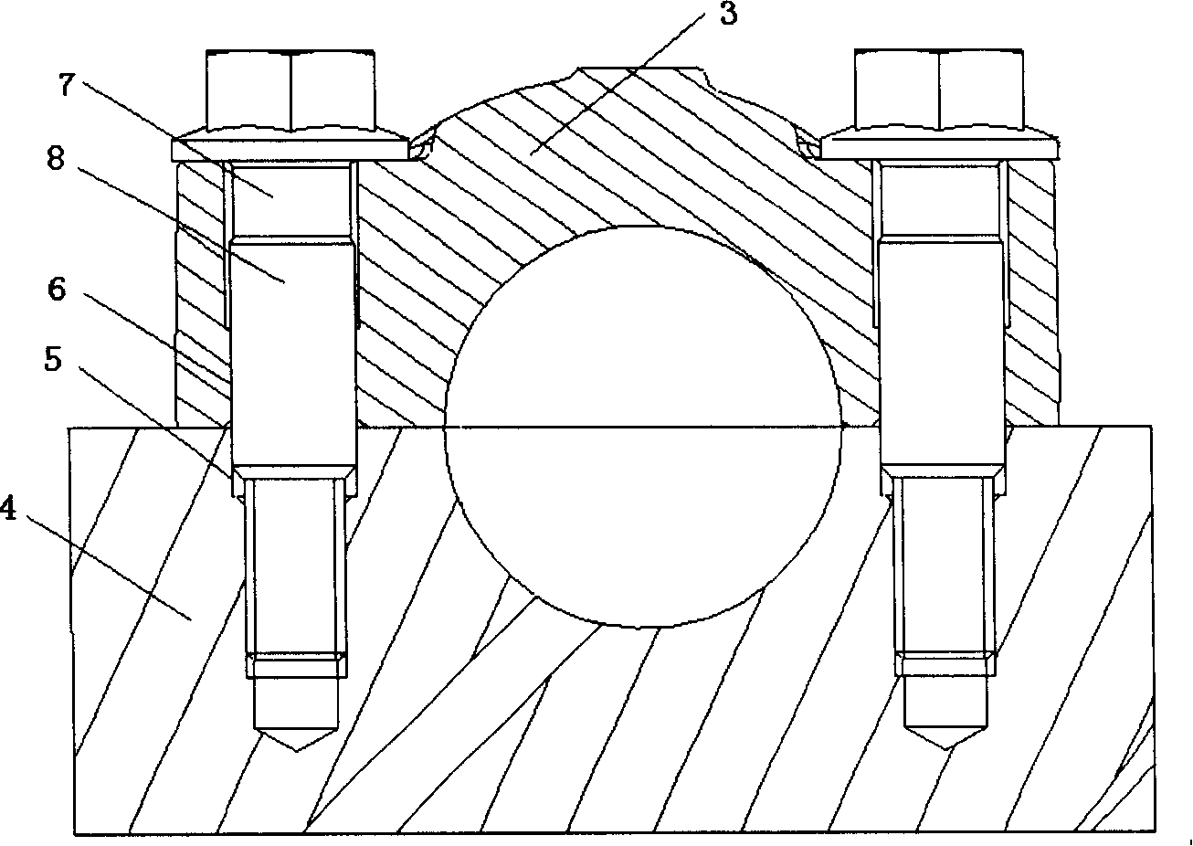
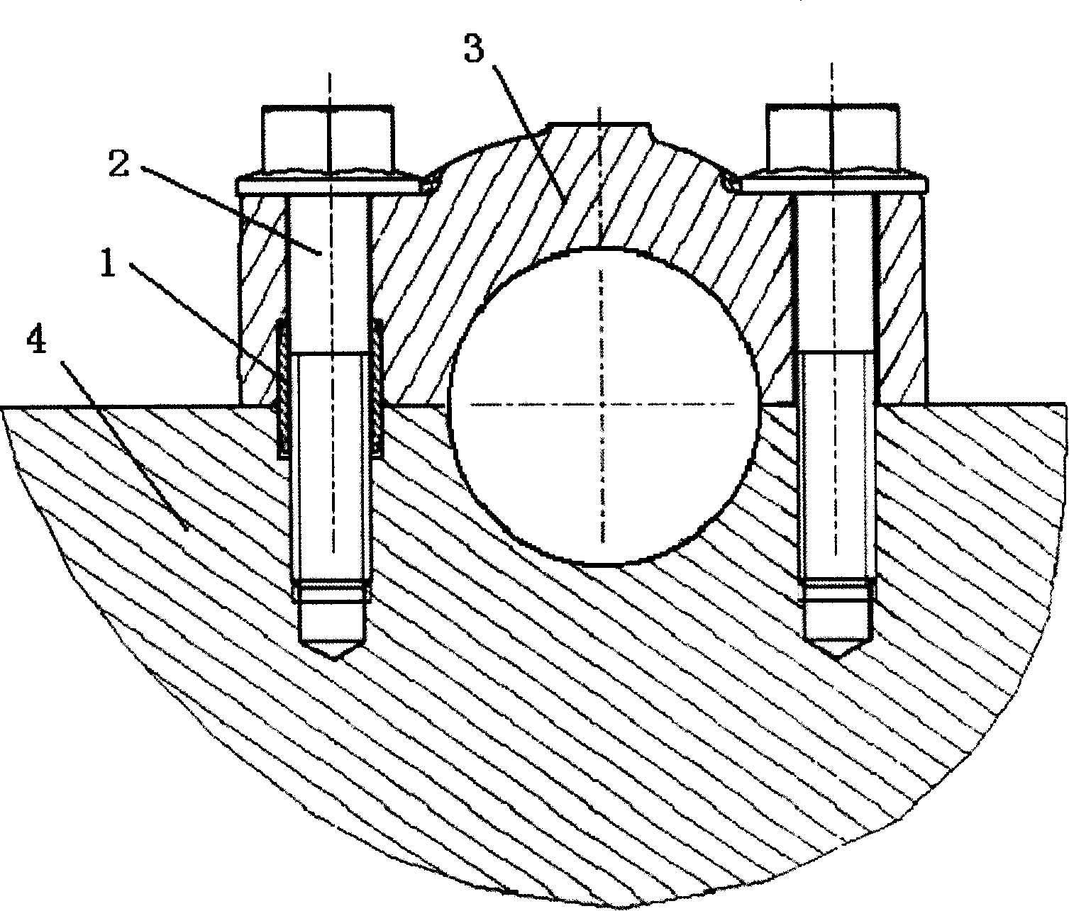
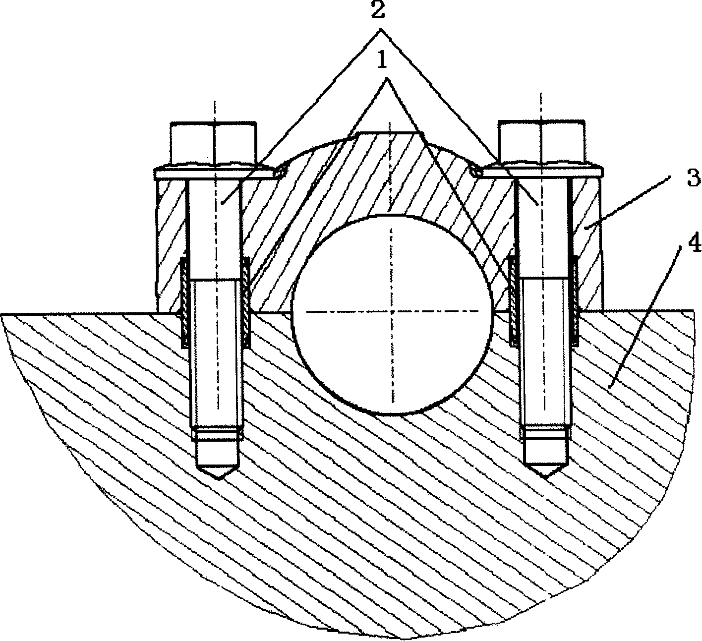
[0024] Embodiment A kind of secondary assembly positioning method, comprises the following main steps:

[0025] 1) Set threaded holes for connection and coaxial positioning holes on the bearing seat cover;

[0026] 2) Set threaded holes for connection and coaxial positioning holes on the bearing seat;

[0027] 3) Insert the positioning connecting bolts into the positioning holes of the bearing seat and bearing cover. The positioning polished rod sections on the positioning connecting bolts are respectively inserted into the positioning holes of the bearing seat and the bearing cover, and the precise clearance fits.

[0028] The method further includes the following steps: setting a pair of threaded holes for connection and coaxial positioning holes on both ends of the bearing seat cover and the bearing seat, so as to accurately limit the degrees of freedom in six directions.

[0029] For the precise clearance fit described in step 3) of the above method, the clearance takes ...


PUM


Abstract

A second assembly positioning method is provided, which comprises the following steps: position a pair of connecting thread hole and coaxial positioning hole on a bearing base cap and two ends of the bearing base; insert a positioning and connecting bolt into the bearing base and the positioning hole of the bearing cap; a positioning polished rod section on the positioning and connecting bolt is respectively inserted into the positioning hole for the bearing base and bearing cap with precise clearance coordination, so as to limit the degree freedom at six directions. The positioning bolt is provided with a nut and a screw; a coaxial positioning polished rod section is arranged at the middle section of the screw; the diameter of the positioning polished rod exceeds that of the screw section. The mutual coordination of the positioning polished rod for the positioning and connecting bolt and the positioning hole of the bearing cap and bearing base realizes the positioning. When the invention is applied for the design of a camshaft bearing cap for engine, the coordination clearance between the camshaft and the bearing hole can be designed smaller, which helps reduce the abnormal noise of engine. In addition, because the positioning rod and bolt integrate into a whole, it needs not to assemble a positioning pin and a positioning sleeve, which realizes excellent economic performance, shorter assembly time and outstanding assembly complexity.

Description

technical field [0001] The invention relates to all occasions where positioning is required for secondary assembly. Specifically, it relates to a secondary assembly positioning method of a bearing cover, in particular to a secondary assembly positioning method of an engine camshaft bearing cover. Background technique [0002] At present, the secondary assembly positioning method, taking the positioning method of the camshaft bearing cap on the vehicle engine as an example, often has three types: [0003] 1. No positioning, without special positioning pins (or positioning sleeves), the bearing cap is directly assembled on the cylinder head with ordinary bolts, and the positioning is performed by the cooperation of the camshaft journal and the bearing hole. This positioning is very imprecise. After the bearing cap bolts are tightened, one translational degree of freedom and two rotational degrees of freedom can be restricted, but the remaining two translational degrees of fre...

Claims


Application Information

Patent Timeline
Patent Type & Authority Applications(China)
IPC IPC(8): F01L1/053
CPCF01L2001/0476
Inventor 宋江龙张文权张德定
Owner CHERY AUTOMOBILE CO LTD
Why Eureka
Try Eureka