Optical plate

A technology of optical board and transparent layer, applied in the field of optical board, can solve the problems of reducing light utilization rate, light energy consumption and loss increase, etc., and achieve the effect of improving light utilization rate, reducing light transmission loss, and reducing the number of interfaces

Inactive Publication Date: 2008-06-11
HONG FU JIN PRECISION IND (SHENZHEN) CO LTD +1
View PDF0 Cites 8 Cited by
  • Summary
  • Abstract
  • Description
  • Claims
  • Application Information

AI Technical Summary

Problems solved by technology

[0004] However, in the prior art, the diffusion plate 13 and the prism sheet 15 are prepared separately, which makes the diffusion plate 13 and the prism sheet 15 independent of each other. During use, although the diffusion plate 13 and the prism sheet 15 can be in close contact, there is still a gap between the diffusion plate 13 and the prism sheet 15. There will be a fine air barrier layer; when the light propagates between the diffuser plate 13 and the prism sheet 15 and passes through the air barrier layer, the light will easily occur at the interface between the air barrier layer and the diffuser plate 13 and the prism sheet 15. Interface reflection and other effects increase the consumption and loss of light energy, thereby reducing the utilization rate of light

Method used


Image

  • Optical plate
  • Optical plate
  • Optical plate

Examples


Embodiment Construction

[0016] The optical plate will be further described in detail with reference to the accompanying drawings and embodiments.

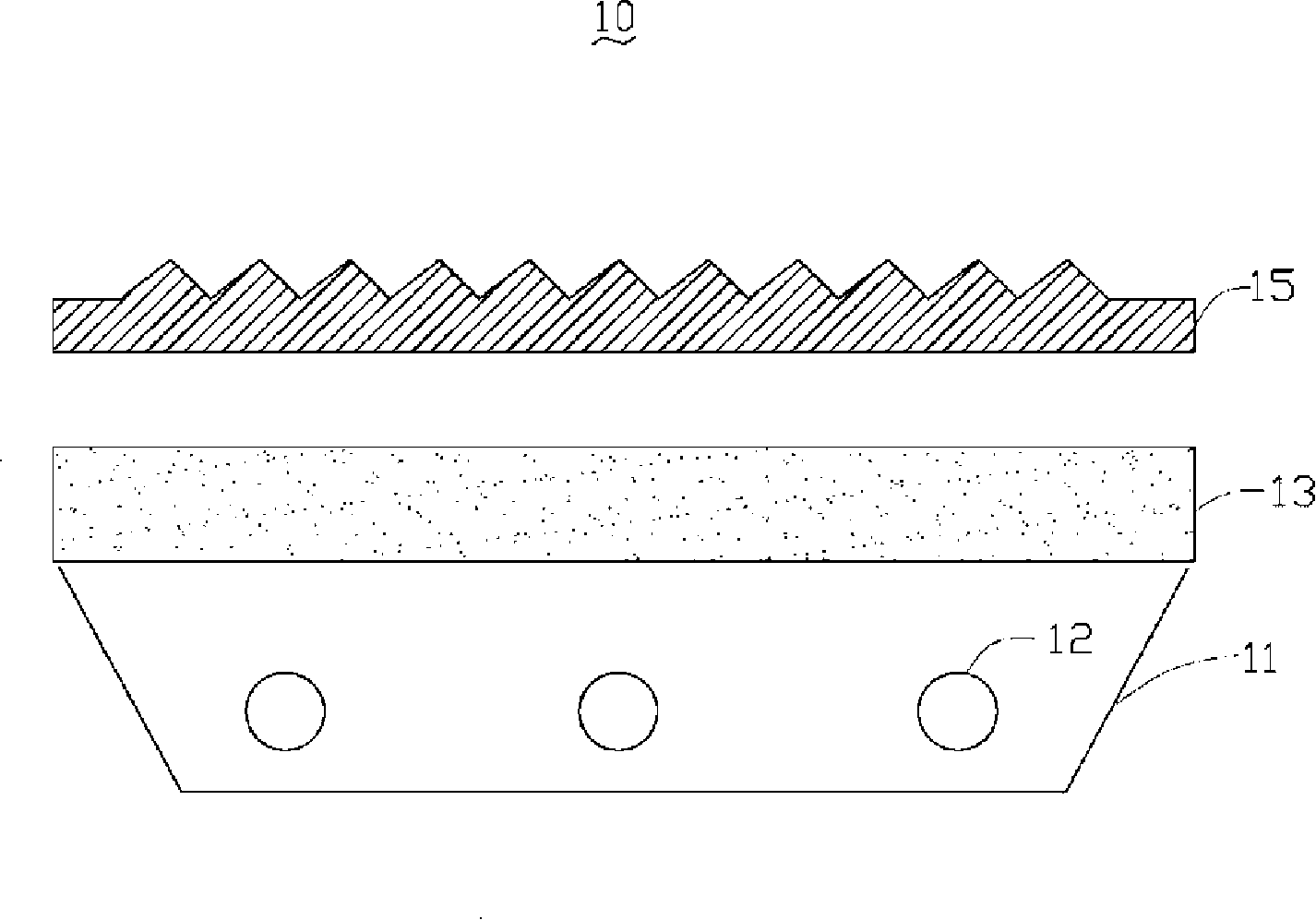
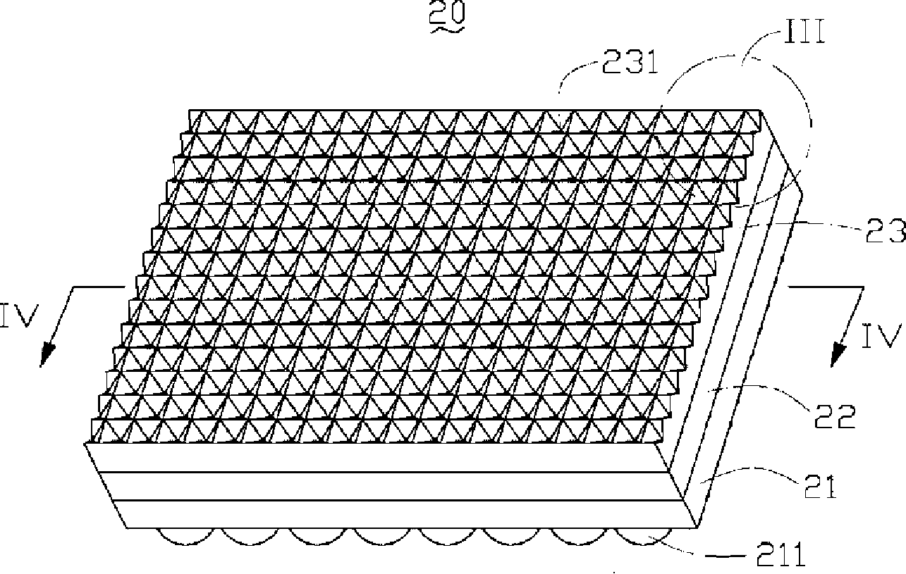
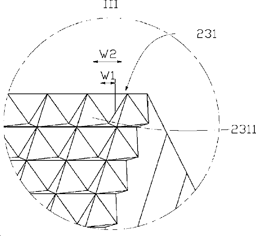
[0017] See figure 2 , the optical plate 20 according to the preferred embodiment 1 of the present invention includes a first transparent layer 21 , a diffusion layer 22 and a second transparent layer 23 integrally formed. The diffusion layer 22 is located between the first transparent layer 21 and the second transparent layer 23 . The outer surface of the first transparent layer 21 opposite to the diffusion layer 22 has a plurality of spherical protrusions 211 . The outer surface of the second transparent layer 23 opposite to the diffusion layer 22 has a plurality of grooves 231, and each groove 231 may include at least three interconnected inner surfaces, and the horizontal width of the inner surfaces is along the direction away from the diffusion layer 22. direction gradually increases. See also image 3 Specifically, in this embodiment, each groov...


PUM

PropertyMeasurementUnit
thicknessaaaaaaaaaa
radiusaaaaaaaaaa
distanceaaaaaaaaaa

Abstract

The invention discloses an optical plate which comprises a first diaphanotheca, a diffusion layer and a second diaphanotheca all-in-one. The diffusion layer is between the first diaphanotheca and the second diaphanotheca, which comprises translucent resin and diffusion particles diffused in the translucent resin. On the surface of the first diaphanotheca opposite to the diffusion layer are a plurality of spherical heaves and on the surface of the second diaphanotheca opposite to the diffusion layer are a plurality of grooves. At least three connected side walls are included in each small groove and the horizontal clearance of each side wall is augmented along the direction away from the diffusion layer. The optical plate is characterized in that the optical plate can elevate the utilization rate of the ray.

Description

technical field [0001] The invention relates to an optical plate for a backlight module, in particular to a composite optical plate. Background technique [0002] Liquid crystal display devices are widely used in electronic products such as personal digital assistants, notebook computers, digital cameras, mobile phones, and LCD TVs. However, since the liquid crystal display device itself cannot emit light, it needs a backlight module to produce a display function. [0003] See figure 1 , a schematic cross-sectional view of a backlight module using an existing optical plate. The backlight module 10 includes a reflector 11 , and above the reflector 11 sequentially includes a plurality of light sources 12 , a diffusion plate 13 and a transparent prism sheet 15 . Among them, the diffusion plate 13 generally contains methyl methacrylate fine particles, and the methyl methacrylate fine particles serve as diffusing particles for diffusing light. The prism sheet 15 has a V-shape...

Claims


Application Information

Patent Timeline
Patent Type & Authority Applications(China)
IPC IPC(8): G02B5/02G02B1/04G02F1/1335
CPCG02B3/0056G02B5/045G02B5/02
Inventor 许东明章绍汉
Owner HONG FU JIN PRECISION IND (SHENZHEN) CO LTD
Why Eureka
Try Eureka