Relay connector

A technology for relay connectors and coaxial connectors, applied in the direction of connection, test/measurement connectors, conductive connections, etc., can solve uneconomical, cumbersome melting soldering operations, and coaxial connector soldering operations cumbersome and other issues, to achieve the effect of reliable electrical connection

Inactive Publication Date: 2008-06-11
YOKOWO CO LTD
View PDF1 Cites 3 Cited by
  • Summary
  • Abstract
  • Description
  • Claims
  • Application Information

AI Technical Summary

Problems solved by technology

[0003] In the structure shown in FIG. 9 and FIG. 10, the soldering operation when electrically connecting the coaxial connectors 14, 14... to the substrate 10 is cumbersome.
In addition, the work of melting the solder when the coaxial connectors 14, 14... are removed from the substrate 10 is also cumbersome.
Moreover, when soldering and melting the solder, heating the dielectric member made of a resin member as a component of the coaxial connector 14 may cause deformation of the dielectric member and changes in electrical characteristics, and it can be used repeatedly. The number of times is limited, uneconomical

Method used


Image

  • Relay connector
  • Relay connector
  • Relay connector

Examples


Embodiment Construction

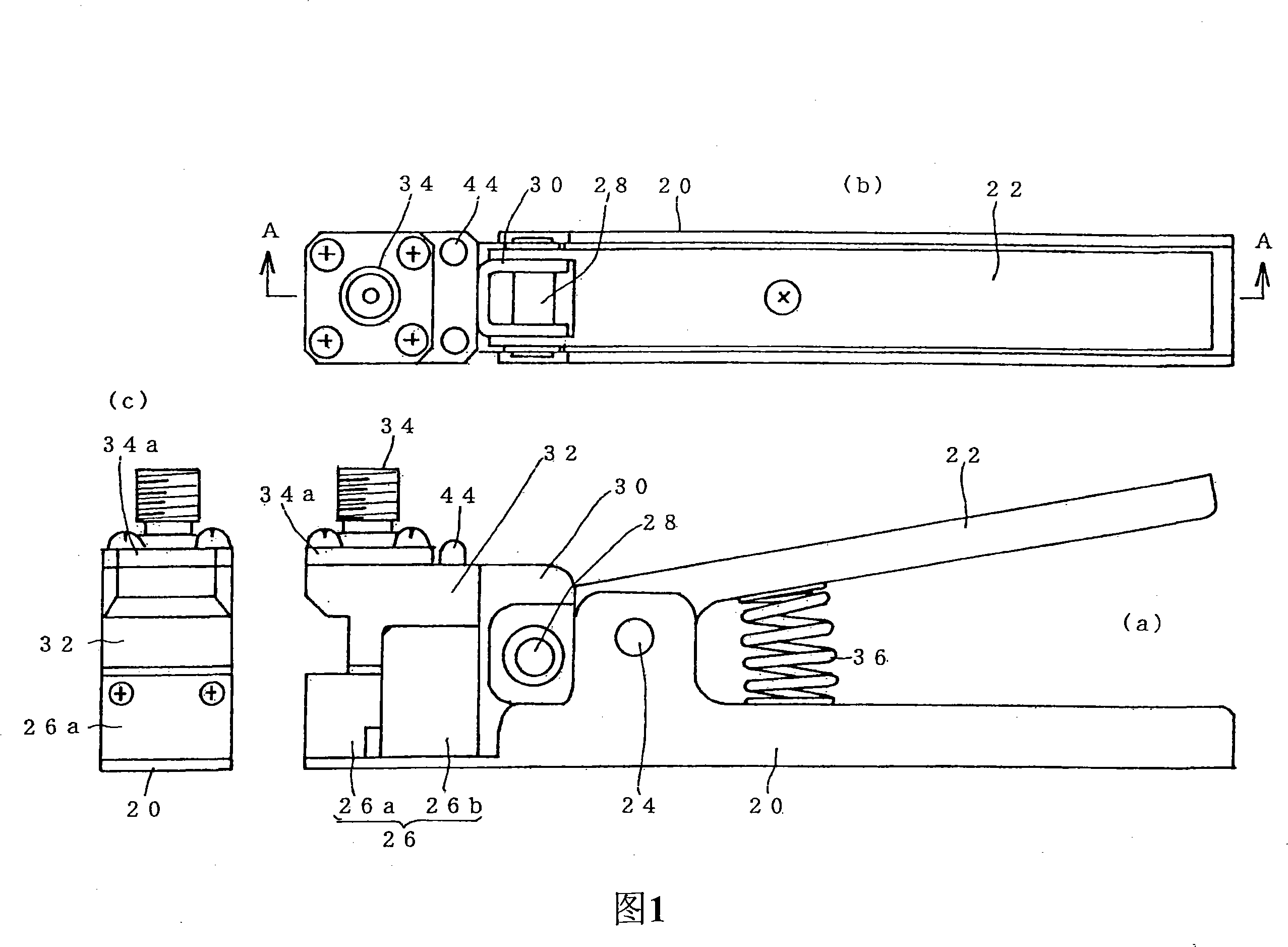
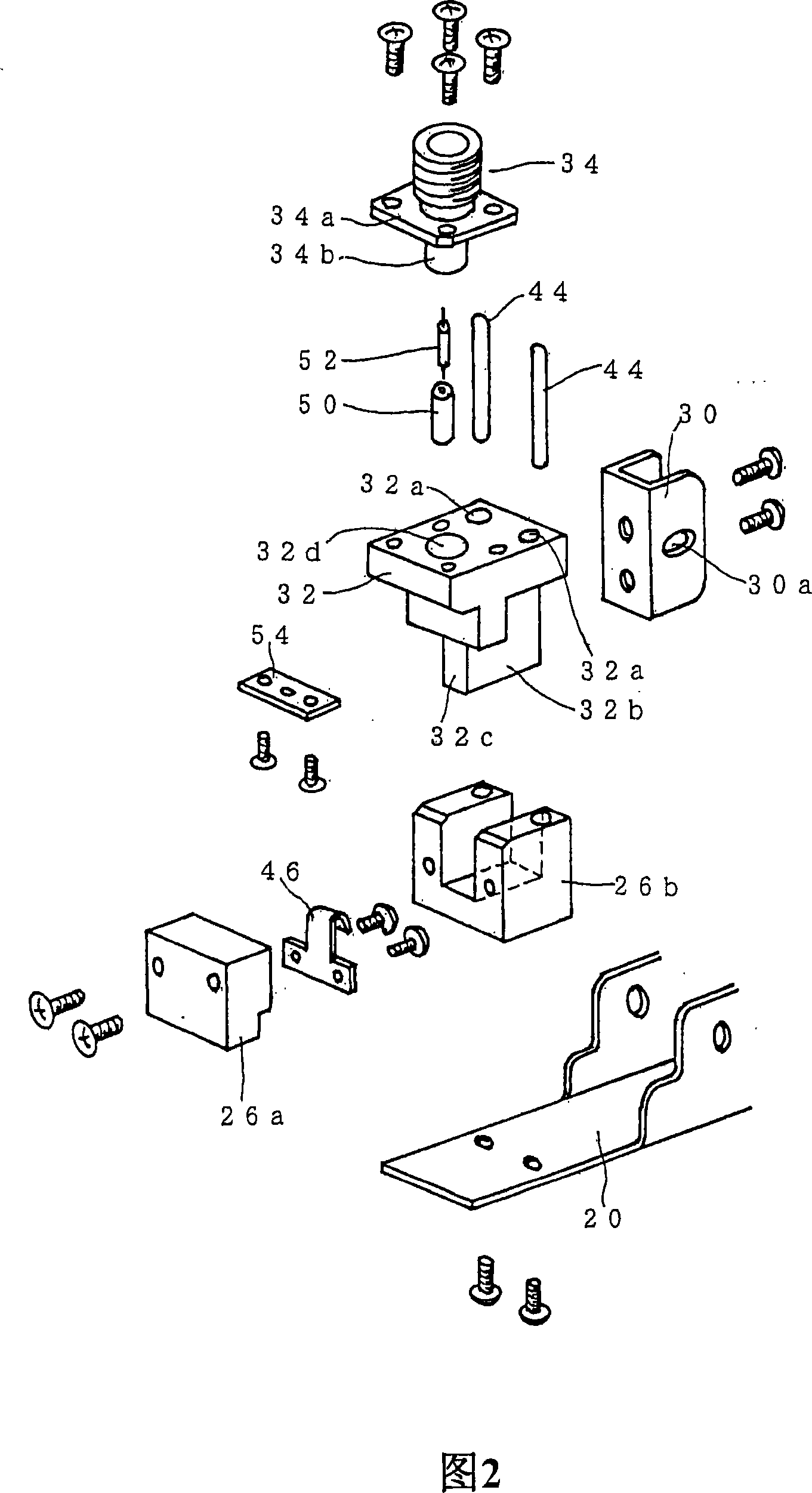
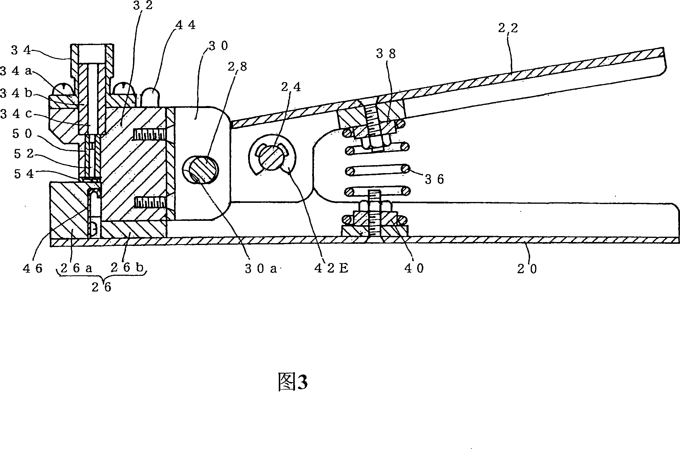
[0068] A first embodiment of the present invention will be described below with reference to FIGS. 1 to 7 . 1 is an external view of a first embodiment of the relay connector of the present invention, (a) is a front view, (b) is a top view, and (c) is a left side view. Fig. 2 is an exploded perspective view of main parts of Fig. 1 . Fig. 3 is a sectional view along A-A of Fig. 1 . 4 is a partially cutaway cross-sectional view in which the substrate is inserted in a state where the first operating lever and the second operating lever are held. 5 is a partially cutaway sectional view showing a state in which the first operating lever and the second operating lever are released to clamp the substrate after the substrate is inserted. Fig. 6 is a partially cutaway enlarged cross-sectional view showing the structure of a portion where an insulating tube is disposed. Fig. 7 is an exploded perspective view of a portion showing a structure in which a leaf spring is arranged. In FIG...


PUM


Abstract

The invention relates to a relay connector which can electrically connect a coaxial connector (34) onto or off a substrate (10), with small-scale and simple operation. A first operating lever and a second operating lever (20 and 22) can sewing so that the substrate GND block (26) and the outer shell GND block (32) made of conductive materials and positioned at one end side of the first operating lever and a second operating lever (20 and 22) can sewing towards to the approaching and separating direction. The coaxial connector (34) is fixed on the outer shell GND block (32). An insulation tube (50) is inserted into a through hole (32d) positioned on the outer shell GND block (32), as well as an inserting core (34c) and a probe (52), wherein, one end of the probe (52) is resisted with the inserting core (34c). an insulation pressing component (54) is arranged on the outer shell GND block (32) in such a way of outstanding the post plug positioned at the other end side while ensuring the probe (52) is unable to be pulled out. The substrate GND block (26) is electrically connected with the outer shell GND block (32). The substrate (10) is clamped by the substrate GND block (26) and the outer shell GND block (32).

Description

technical field [0001] The present invention relates to electrically connecting the core wire of the coaxial connector to the terminal electrode provided on the surface of the substrate and electrically connecting the outer GND of the coaxial connector to the GND electrode provided on the back surface of the substrate for inspection of the substrate, etc. relay connector. Background technique [0002] In the design and manufacture of high-frequency circuit boards, etc., it may be necessary to evaluate their characteristics during design. Then, the core wire of the coaxial connector is electrically connected to the terminal electrode provided on the surface end of the substrate, and the outer contour GND of the coaxial connector is electrically connected to the GND electrode provided on the back end of the substrate. The obtained high-frequency signal is used for characteristic evaluation. A conventional structure for electrically connecting a coaxial connector to a substra...

Claims


Application Information

Patent Timeline
Patent Type & Authority Applications(China)
IPC IPC(8): H01R43/00H01R9/05
CPCG01R1/0416H01R2103/00H01R24/50H01R2201/20H01R13/629
Inventor 铃木久史三浦力
Owner YOKOWO CO LTD
Why Eureka
Try Eureka