
Feed-forward amplifier

A technology for amplifiers and main amplifiers, applied in the field of feedforward amplifiers, which can solve problems such as large distortion, changes in compensation amount of pre-distortion circuits, and inability to completely eliminate pilot signals.

Inactive Publication Date: 2008-06-11
ITACHI KOKUSAI ELECTRIC INC
View PDF1 Cites 11 Cited by
  • Summary
  • Abstract
  • Description
  • Claims
  • Application Information

AI Technical Summary

Problems solved by technology

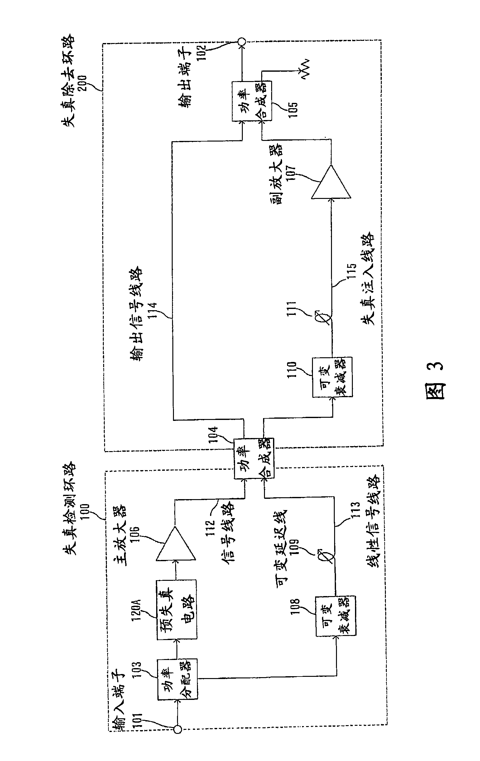
[0037] The second problem is that when the gain of the sub-amplifier 107 changes due to changes in ambient temperature, etc., the compensation amount of the pre-distortion circuit 102B changes, and the distortion of the sub-amplifier 107 cannot be compensated.
[0062] When the ambient temperature of the power amplifier used in the sub-amplifier 14 changes, generally, as shown in FIG. 6(a), the gain decreases at high temperatures.
In addition, the generated distortion also depends on the output power more than the ambient temperature, and as shown in Fig. 6(b), the higher the output level, the larger the distortion
[0063] In the feedforward amplifier of the conventional example 5 shown in FIG. 7, when considering the increase in the ambient temperature, the gain of the auxiliary amplifier 14 decreases as shown in FIG. 6(a) due to the increase in the ambient temperature. However, in this state, the amplitudes of the signal line c and the signal line d are not the same amplitude, so after the synthesizer 9 is synthesized, the injected pilot signal cannot be completely eliminated, and the output from the synthesizer 9 is

Method used


Image

  • Feed-forward amplifier
  • Feed-forward amplifier
  • Feed-forward amplifier

Examples


Embodiment Construction

[0083] [summary of embodiment]

[0084] Embodiments of the present invention will be described with reference to the drawings.

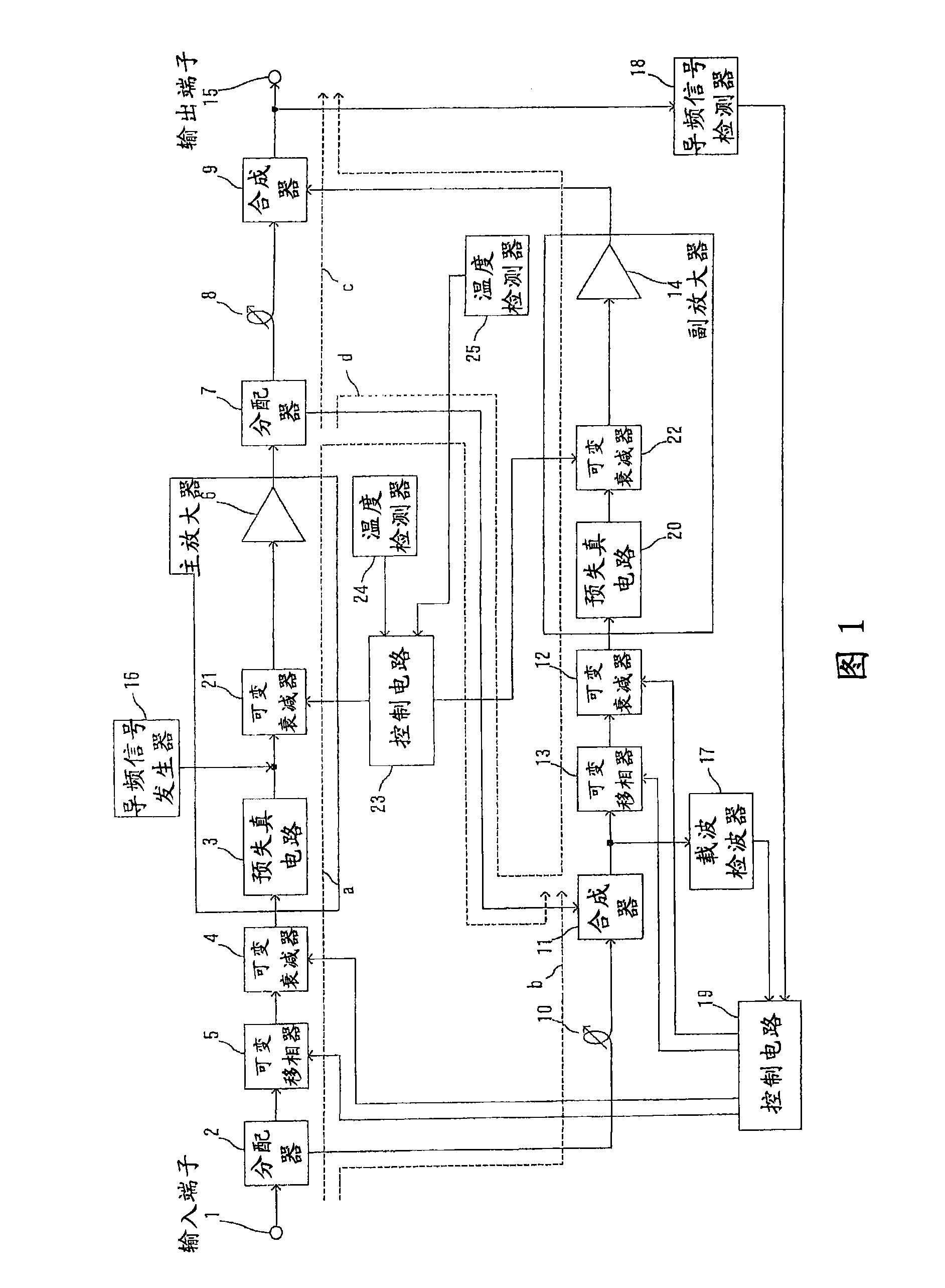
[0085] In a feedforward amplifier with a predistortion circuit, the present invention is useful for optimally controlling the variable attenuator of the feedforward amplifier, and for preventing distortion (distortion) of an amplifier based on a predistortion circuit due to changes in ambient temperature The variable attenuators for compensating for degradation are separated and independently controlled, whereby a sufficient distortion compensation effect can be obtained by the predistortion circuit even when the ambient temperature or the like changes.

[0086] [Overall structure of this amplifier: Figure 1]

[0087] A feedforward amplifier according to an embodiment of the present invention will be described with reference to FIG. 1 . FIG. 1 is a block diagram of a circuit structure of a feedforward amplifier according to an embodiment of the prese...


PUM


Abstract

The present invention provides a feedforward amplifier capable of obtaining a sufficient distortion compensation effect by a predistortion circuit even when the ambient temperature changes. This feed-forward amplifier is provided with a variable attenuator (4) to control the attenuation of the signal input to the main amplifier (6), and the attenuation is controlled in order to prevent deterioration of distortion compensation due to changes in the ambient temperature of the main amplifier (6). A variable attenuator (21), a variable attenuator (12) for controlling the attenuation of the signal input to the sub-amplifier (14), in order to prevent distortion compensation caused by changes in the ambient temperature of the sub-amplifier (14) The variable attenuator (22) that degrades and controls the attenuation, controls the variable attenuator (4,12) with the control circuit (19) so that the gain drop with the main amplifier (6) and the gain of the auxiliary amplifier (14) The amount of drop decreases the attenuation accordingly, and the control circuit (23) controls the variable attenuators (21, 22) so as to become the optimum temperature corresponding to the ambient temperature of the main amplifier (6) and the ambient temperature of the sub-amplifier (14). good attenuation.

Description

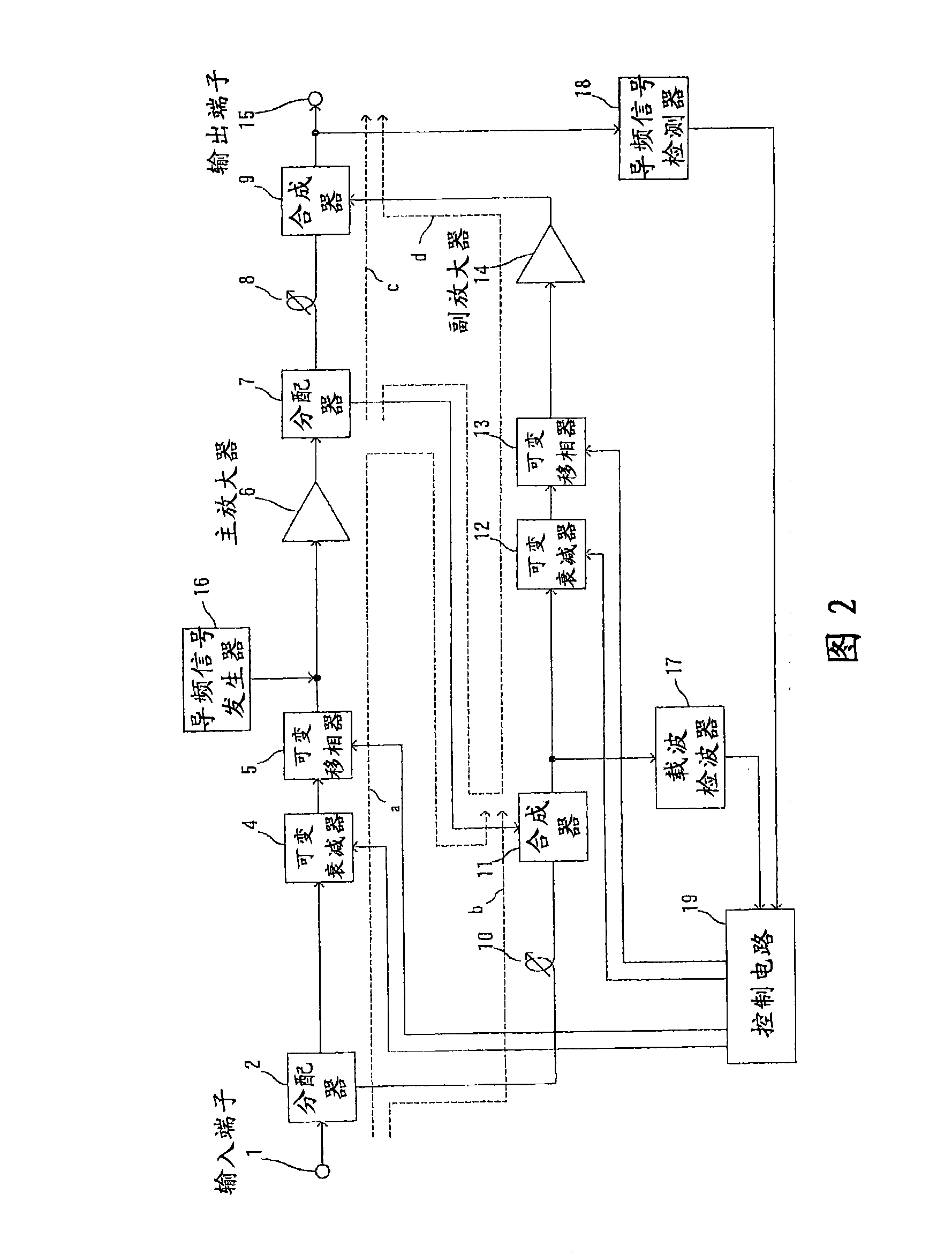
technical field [0001] The present invention relates to a feed-forward amplifier having a pre-distortion circuit (pre-distortion compensator), and more particularly to a feed-forward amplifier capable of obtaining a distortion compensation effect by the pre-distortion circuit even when the ambient temperature changes. Background technique [0002] In recent years, various developments have been made regarding feedforward amplifiers. [0003] In a feedforward amplifier, when amplifying a modulated wave signal with a high peak-to-average power ratio, the linearity deteriorates and large distortion occurs when the compensation of the amplifier is reduced in order to improve efficiency ( distortion). Conversely, when the compensation is increased in order to improve linearity, the efficiency will deteriorate. [0004] [Existing Example 1: Figure 2] [0005] For example, as a method of compensating nonlinear distortion (nonlinear distortion) caused by small compensation, there...

Claims


Application Information

Patent Timeline
Patent Type & Authority Applications(China)
IPC IPC(8): H03F1/32H03F3/20
CPCH03F1/3223H03F1/3241
Inventor 岩崎隆司
Owner ITACHI KOKUSAI ELECTRIC INC
Learn More