

Heat exchanger
A technology of heat exchange equipment and heat exchange elements, which is applied in the directions of heat exchange equipment, lighting and heating equipment, household heating, etc., can solve problems such as difficult configuration engineering, and achieve the effect of reducing pressure loss and high heat exchange performance
- Summary
- Abstract
- Description
- Claims
- Application Information
AI Technical Summary
Problems solved by technology
Method used
Image

Examples
Embodiment approach 1
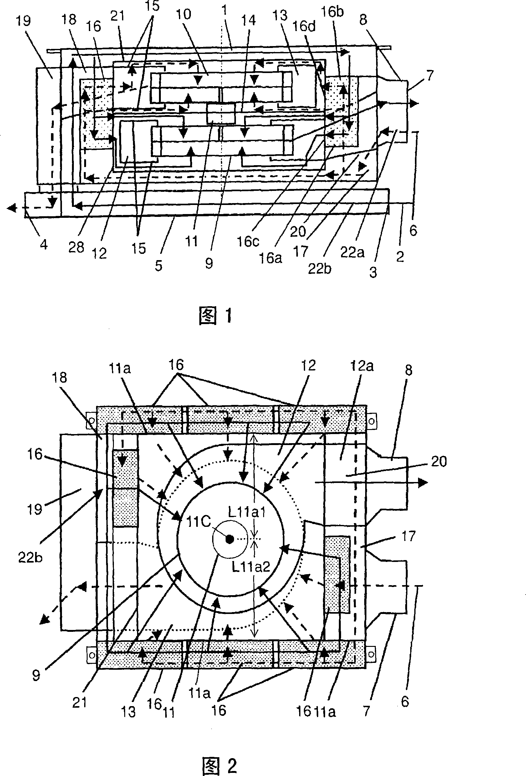
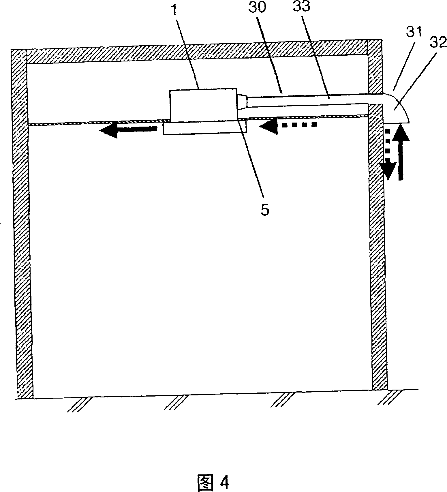
[0049] Embodiment 1 of the present invention will be described based on FIGS. 1 to 4 .
[0050] As shown in Figures 1 and 2, on the box-shaped body 1, a louver 5 having an indoor suction port 3 for sucking in indoor air 2, an indoor air outlet 4 for blowing air into the room, and an outdoor window for sucking in outdoor air 6 are provided on the side of the box-shaped body 1. Suction port 7, the outdoor air outlet 8 that blows out air to the outside. In the central part of the body 1, a motor 11 is provided with an exhaust blade 9 and an air supply blade 10 that blow air as it rotates.
[0051] Furthermore, the motor 11 is disposed on a motor fixing plate 14 provided between the exhaust fan case 12 and the air supply fan case 13 . The distance from the suction surface 15 of the exhaust fan case 12 to the motor fixing plate 14 is equal to the distance from the suction surface 15 of the air supply fan case 13 to the motor fixing plate 14 . In addition, an exhaust fan case 12 i...
Embodiment approach 2
[0071] Fig. 5 is a side sectional view showing a supporting structure of the motor, and Fig. 6 is a state in which the motor is mounted on the ceiling. In FIGS. 5 and 6 , the same reference numerals are used for the same parts as those in FIGS. 1 to 4 . As shown in Fig. 5 and Fig. 6, two supporting members 38 are fixed on two opposite sides 37 of the body 1, the motor fixing plate 14 is fixed on the two supporting members 38, and the motor 11 is fixed on the motor fixing plate 14. . In addition, two hangers 39 are respectively fixed to the two support members 38 .
[0072] Based on the above configuration, the weight of the motor 11 is held by the four hangers 39 via the motor fixing plate 14 and the two support members 38 .
[0073] Therefore, when the machine body 1 is suspended, the weight of the electric motor 11 as a heavy object can be sufficiently supported by the supporting member 38 . Therefore, since the body 1 having a large surface area does not require much str...
Embodiment approach 3
[0075] Embodiment 3 will be described based on FIG. 7 and FIG. 8 . Fig. 7 is a front sectional view of the heat exchange device, and Fig. 8 is a bottom sectional view. In FIGS. 7 and 8 , the same reference numerals are used for the same parts as those in FIGS. 1 to 6 .
[0076] Compared with Embodiment 1, which directly performs indoor air supply and exhaust, Embodiment 3 differs from it in that the indoor air supply and exhaust are carried out from the main body through pipes.
[0077] As shown in Fig. 7 and Fig. 8, the indoor suction port 3 for sucking in indoor air 2 and the indoor blowing port 4 for blowing air indoors and the outdoor suction port 7 for sucking in outdoor air 6 and blowing out air to the outside are set on the side of the box-shaped body 1. The outdoor blowing outlet 8 of air. In the central part of the body 1, a motor 11 is provided with an exhaust blade 9 and an air supply blade 10 that blow air as it rotates. The motor 11 is arranged on the motor fix...
PUM
 Abstract
Description
Claims
Application Information