Spinning nozzle

A technology of spinning nozzle and spinning hole, which is applied in the field of inserted tubular porous spinning nozzle, which can solve the problems of abnormal production and loss of concentricity, etc., and achieve the effects of easy assembly, guaranteed spinning quality and convenient use

Inactive Publication Date: 2008-06-18
胡萍
View PDF1 Cites 4 Cited by
  • Summary
  • Abstract
  • Description
  • Claims
  • Application Information

AI Technical Summary

Problems solved by technology

However, in practical applications, it is found that after adjusting the concentricity at room temperature, under the condition of heating, the concentricity is lost due to the release of metal deformation stress, so it cannot be produced normally.

Method used


Image

  • Spinning nozzle
  • Spinning nozzle
  • Spinning nozzle

Examples


Embodiment Construction

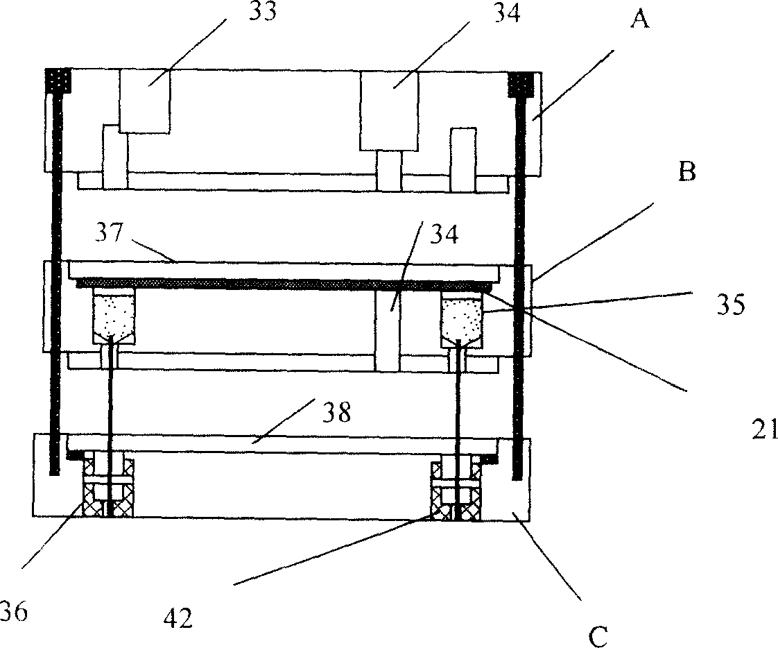
[0018] The following is based on figure 1 -4 Describe in detail the specific structure of the spinneret of the present invention.

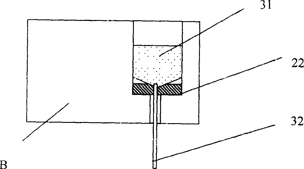
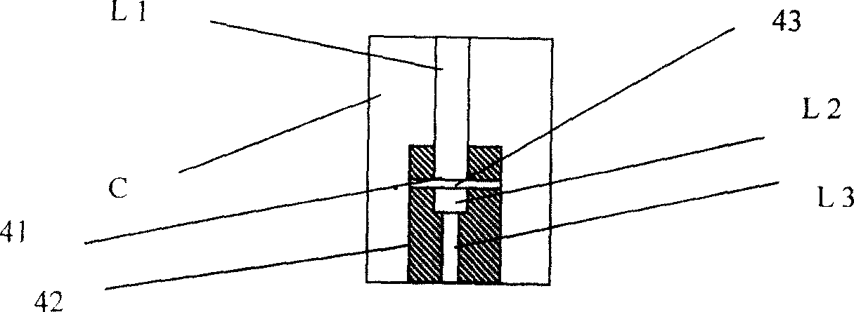
[0019] Such as figure 1 As shown, the spray head of the present invention is composed of upper assembly A, middle assembly B, and lower assembly C as a whole. Such as figure 1 As shown, the upper component A is provided with a core liquid hole 33 and a liquid material hole 34; the middle component B is provided with a liquid material hole 34 and a socket hole 35, and the socket 31 of the insertion tube is embedded in the socket hole 35. The top of the intermediate assembly B is provided with a core liquid tank 37; the lower assembly C is provided with a spinneret hole 36, and a cylinder 42 is arranged in the spinneret hole 36, and the middle of the cylinder 42 is perforated for the insertion tube 32 to pass through. A liquid material tank 38 is arranged on the top.

[0020] More specifically, the insertion tube may be a needle for injection. ...


PUM


Abstract

The invention relates to a chemical fiber spinning nozzle, in particular to an inserted pipe type porous spinning nozzle which is used for spinning hollow fiber. According to the inserted pipe type hollow fiber spinning nozzle provided by the invention, the nozzle includes an upper component, a middle component and a lower component. A core liquid hole and a liquid material hole are arranged on the upper component; a liquid material hole and a socket hole are arranged in the middle component; the socket hole is embedded in the socket of an inserted pipe; a spinneret hole is arranged on the lower component; a cylinder is arranged in the spinneret hole; a hole is arranged in the middle of the cylinder for the inserted pipe to pass through for the compulsory concentric location. According to the nozzle structure of the invention, the concentration of the nozzle is not needed to be regulated. Thus, the invention can be easily disassembled for cleaning whenever the spinning is finished. The assembly is easy. And the concentration of the nozzle is not needed to be regulated again. With convenient usage, the invention can guarantee the spinning quality and is beneficial to be used in the large scale production.

Description

technical field [0001] The invention relates to a chemical fiber spinning nozzle, in particular to an insertion tube type porous spinning nozzle for spinning hollow fibers. Background technique [0002] Spinneret is the key component of spinning hollow fiber in spinning machine. Spinning hollow fiber generally adopts the insertion tube type spinning nozzle, its working principle is to flow out the spinning core liquid in the insertion tube to form the inner cavity of the hollow fiber, and spray the spinning stock solution in the ring gap between the outer wall of the insertion tube and the spinning hole , forming hollow fiber walls. Therefore, the concentricity of the insertion tube and the spinning hole directly affects the uniformity of the wall thickness of the spun hollow fiber, that is, the quality of the hollow fiber. [0003] Due to the fixed tube seat structure of the currently used insertion tube spinning nozzle, the position of the insertion tube in the spinning ...

Claims


Application Information

Patent Timeline
Patent Type & Authority Applications(China)
IPC IPC(8): D01D5/24D01D7/00
Inventor 胡萍
Owner 胡萍
Why Eureka
Try Eureka