Multiple shaft directions warp knitting machine

A multi-axial, warp knitting machine technology, applied in flat warp knitting machines, warp knitting, textiles and papermaking, etc., can solve problems such as increasing the risk of yarn breakage, and achieve the effect of avoiding yarn tension fluctuations

Active Publication Date: 2008-06-18
KARL MAYER MALIMO TEXTILMASCHFAB
View PDF1 Cites 11 Cited by
  • Summary
  • Abstract
  • Description
  • Claims
  • Application Information

AI Technical Summary

Problems solved by technology

This also increases the risk of yarn breakage

Method used


Image

  • Multiple shaft directions warp knitting machine
  • Multiple shaft directions warp knitting machine
  • Multiple shaft directions warp knitting machine

Examples


Embodiment Construction

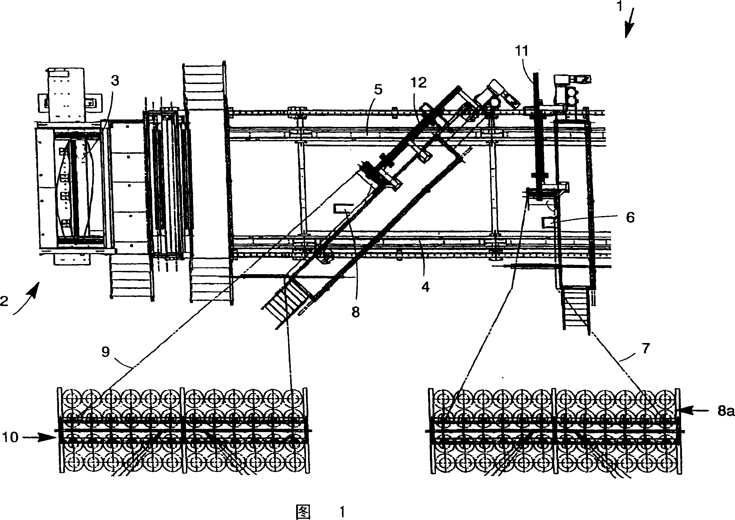
[0021] The multiaxial warp knitting machine 1 has a knitting machine 2 which in turn has a knitting zone 3 which, as will be explained below, serves as a curing device.

[0022] A conveying device consisting of a first longitudinal conveyor 4 and a second longitudinal conveyor 5 is provided for conveying the yarn to the knitting zone 3 . The yarns are placed here in layers on the longitudinal conveyors 4 , 5 .

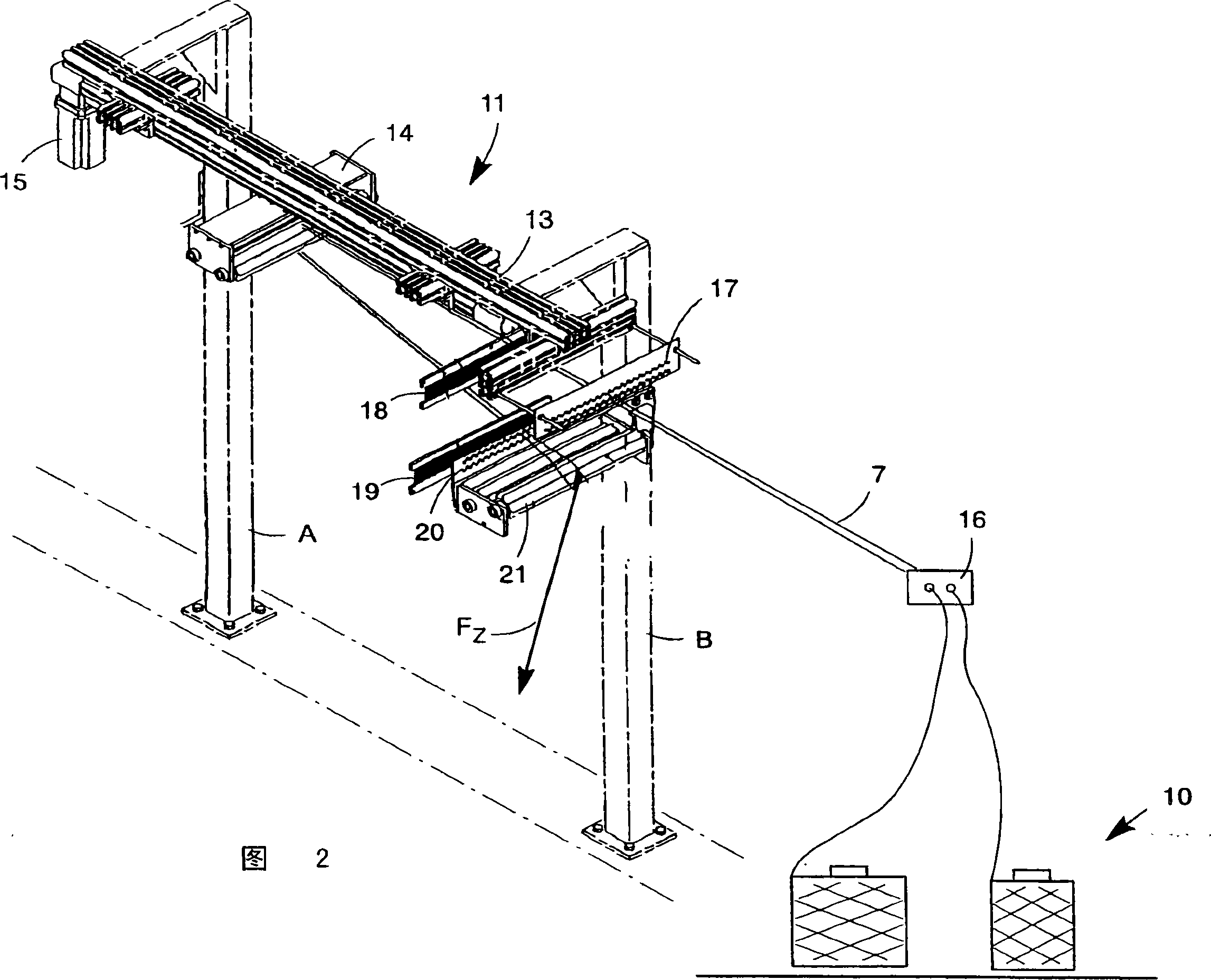
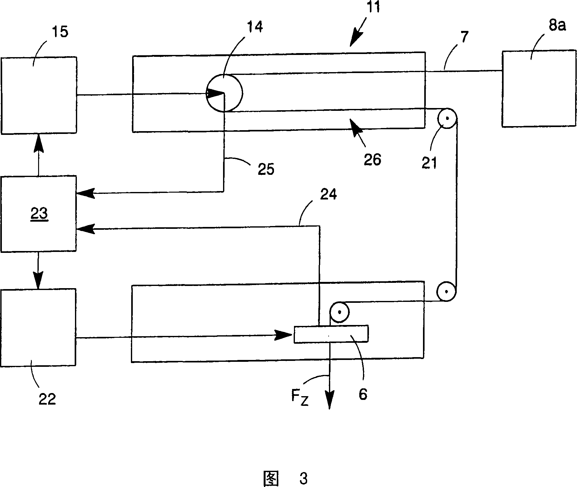
[0023] Furthermore, a first laying device 6 is provided, which withdraws the yarn 7 from the warp creel 8a and places it on the longitudinal conveyors 4, 5 at an angle of 90° with respect to the direction of movement of the longitudinal conveyors 4, 5. 4, 5 above or inside. A second laying device 8 is provided, which draws out the yarns 9 from the warp creel 10 and takes these yarns 9 as yarn layers at an angle of about 45° relative to the direction of movement of the longitudinal conveyors 4, 5. Placed on or in said longitudinal conveyors 4 , 5 .

[0024] In a know...


PUM


Abstract

The invention relates to a multi-axial warp knitting machine (1), comprising a yarn laying device (6) which is moved through a first driving device (22), a yarn storing device and a yarn depositing device (11) arranged between the yarn storing device and the yarn laying device (6), wherein, the yarn laying device is provided with at least one yarn layer on or inside a conveying device through which the yarn layer can be conveyed to a solidifying device. The invention provides multi-axial warp knitting machine with high productivity. Therefore, the yarn depositing device (11) is provided with a yarn storing section (26) whose length is changed through a second driving device (15), wherein, the second driving device (15) is connected with a control device (23) which controls the second driving device (15) according to the movement of the yarn laying device (6).

Description

technical field [0001] The invention relates to a multiaxial warp knitting machine with a yarn laying device moved by a first drive, a yarn storage device and a yarn storage device arranged between the yarn storage device and the yarn laying device. The yarn storage device of the present invention, wherein the yarn laying device places at least one yarn layer on or in the conveying device, and the yarn layer can be conveyed to the curing device by the conveying device. Background technique [0002] Such a multiaxial warp knitting machine is known, for example, from DE 10 2004 012 305 B3. The conveying device is formed by two conveying chains, which each have a plurality of guide hooks, in which guide hooks the yarn of the yarn layer is placed. In this case, the yarn laying device is moved transversely to the conveying direction of the conveying device or at any angle greater than 0° for depositing the yarn layers. The yarns forming the yarn layers are withdrawn from a yarn...

Claims


Application Information

Patent Timeline
Patent Type & Authority Applications(China)
IPC IPC(8): D04B23/12D04B27/10D04H3/045
CPCD04B23/12D04H3/045
Inventor S·佩特伦茨A·韦格纳S·尤利格
Owner KARL MAYER MALIMO TEXTILMASCHFAB
Why Eureka
Try Eureka