Portable diagnostic apparatus and the method thereof
A diagnostic device, portable technology, used in the field of systems for detecting analytes, capable of resolving discrepancies, misinterpretations, etc.
- Summary
- Abstract
- Description
- Claims
- Application Information
AI Technical Summary
Problems solved by technology
Method used
Image

Examples
example 1
[0119] 1. Equipment
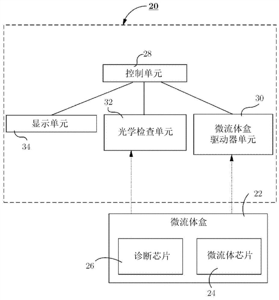
[0120] figure 1 and figure 2 A diagnostic system is shown that includes (1) a diagnostic device 20 and (2) a microfluidic cartridge 22 that operates with the diagnostic device 20 . Microfluidic cartridge 22 containing microfluidic chip 24 and diagnostic chip 26 is configured to collect and manipulate at least one sample, which may contain at least one analyte. Microfluidic cartridge 22 also houses and / or holds at least one reagent. The diagnostic device 20 is a portable, hand-held and compact device comprising a control unit 28 , a microfluidic cartridge driver unit 30 , an optical inspection unit 32 and a display unit 34 . The control unit 28 controls and is connected to a microfluidic cartridge driver unit 30 , an optical inspection unit 32 and a display unit 34 . The microfluidic cartridge driver unit 30 is configured to accommodate and drive the microfluidic cartridge 22 such that collected samples and reagents pass through the microfluidic chip...
example 2
[0202] 2. Microfluidic cartridge
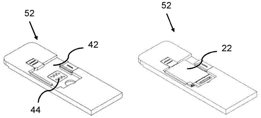
[0203] Such as Figure 6A , Figure 6B and Figure 6C The microfluidic cartridge 22 shown in FIG. 2 contains a diagnostic chip 26 affixed to a microfluidic chip 24 . In the embodiment shown it is smaller in size than a credit card and has a thickness of 1-10mm. The microfluidic chip 24 includes an electrical connection interface 78 for receiving control signals and power provided through the electrical connector 44 of the cartridge chamber 42 , a top portion 68 and a bottom portion 70 attached to the top portion 68 . In this example, top portion 68 and bottom portion 70 are assembled together by adhesive material or by a welding process. The bottom portion 70 may be made of an electrically insulating material such as plastic and resin materials. Such as Figure 6A As shown in , top portion 68 has a plurality of microgrooves 66, channel openings for fluid connection with microfluidic chip 24, and adhesive 74 for attaching microfluidic ch...
example 3
[0226] Test Methods
[0227] Another exemplary embodiment provides an on-site diagnostic method and operation of a diagnostic system. Reagents to facilitate analyte detection are preloaded into separate reservoirs 80 and sealed during the manufacturing process. Reagents held in at least one reservoir are selected from the group consisting of wash buffer (eg, PBS), blocking buffer (eg, bovine serum albumin (BSA)), lysis buffer (eg, PBS), Antigens, antibodies, and fluorophores (eg, fluorescein in PBS). In one embodiment, the wash buffer is PBS and the blocking buffer is PBS and BSA. In an exemplary embodiment, the microfluidic cartridge contains 5-12 reservoirs for holding reagents or samples. In some embodiments, the reagent volume is between 20-200ul. In some embodiments, the reagent volume is 50 uL. Reagents can be stored in one or more reservoirs. For example, if the capacity of one reservoir is insufficient to hold all required volumes of a particular reagent, additio...
PUM
| Property | Measurement | Unit |
|---|---|---|
| Wavelength | aaaaa | aaaaa |
| Excitation wavelength | aaaaa | aaaaa |
| Wavelength | aaaaa | aaaaa |
Abstract
Description
Claims
Application Information
 - Generate Ideas
- Intellectual Property
- Life Sciences
- Materials
- Tech Scout
- Unparalleled Data Quality
- Higher Quality Content
- 60% Fewer Hallucinations
Browse by: Latest US Patents, China's latest patents, Technical Efficacy Thesaurus, Application Domain, Technology Topic, Popular Technical Reports.
© 2025 PatSnap. All rights reserved.Legal|Privacy policy|Modern Slavery Act Transparency Statement|Sitemap|About US| Contact US: help@patsnap.com