Free door controller

A free, door frame technology, applied to switches with brakes, door/window accessories, wing openers, etc., can solve the problems of difficult operation, complicated installation procedures, time-consuming and laborious maintenance, etc. Wide range of uses and the effect of expanding the scope of application

Inactive Publication Date: 2008-06-18
初恒毅
View PDF0 Cites 8 Cited by
  • Summary
  • Abstract
  • Description
  • Claims
  • Application Information

AI Technical Summary

Problems solved by technology

The installation process is complicated, the operation is difficult, and the maintenance is time-consuming and laborious

Method used


Image

  • Free door controller
  • Free door controller
  • Free door controller

Examples


Embodiment 1

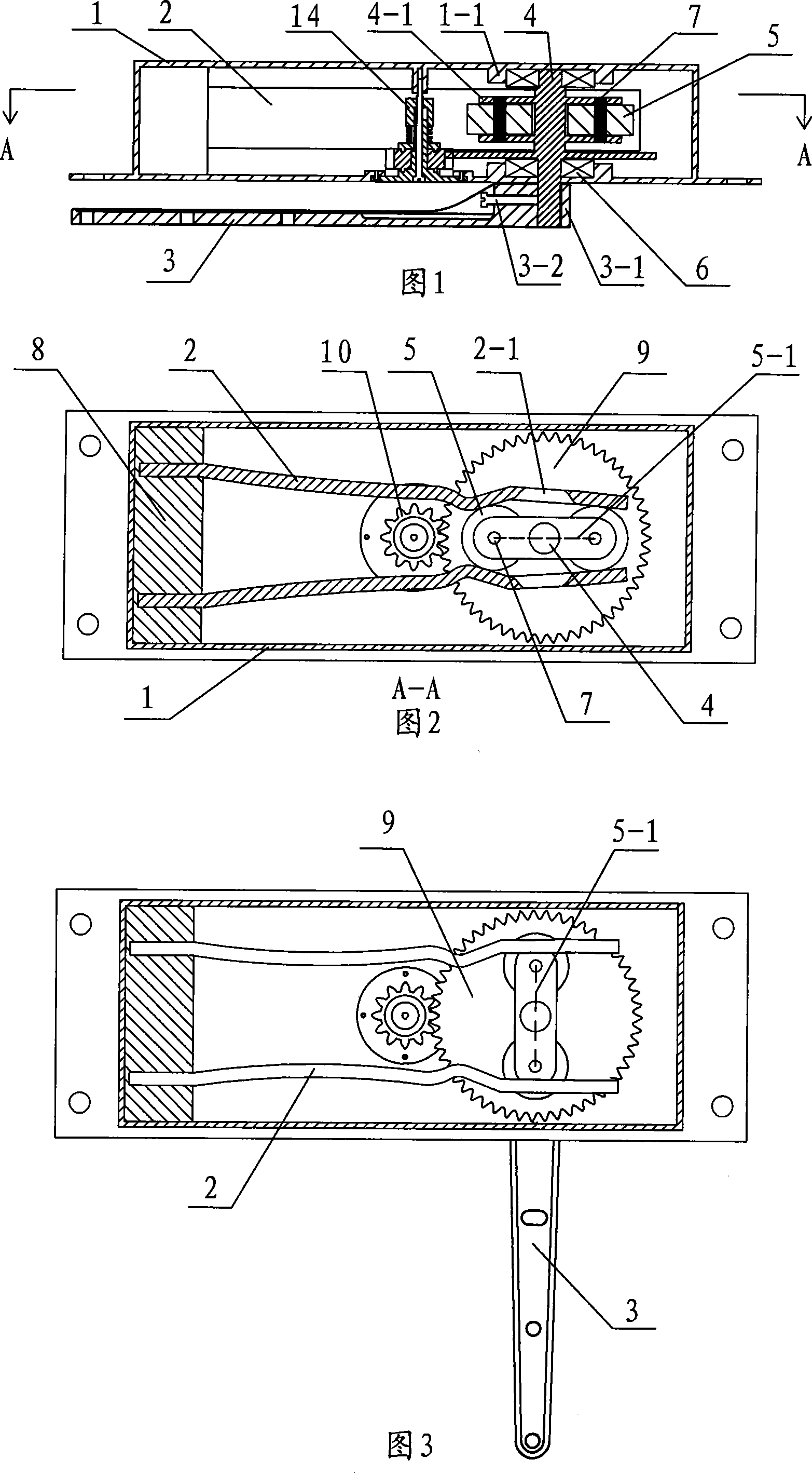
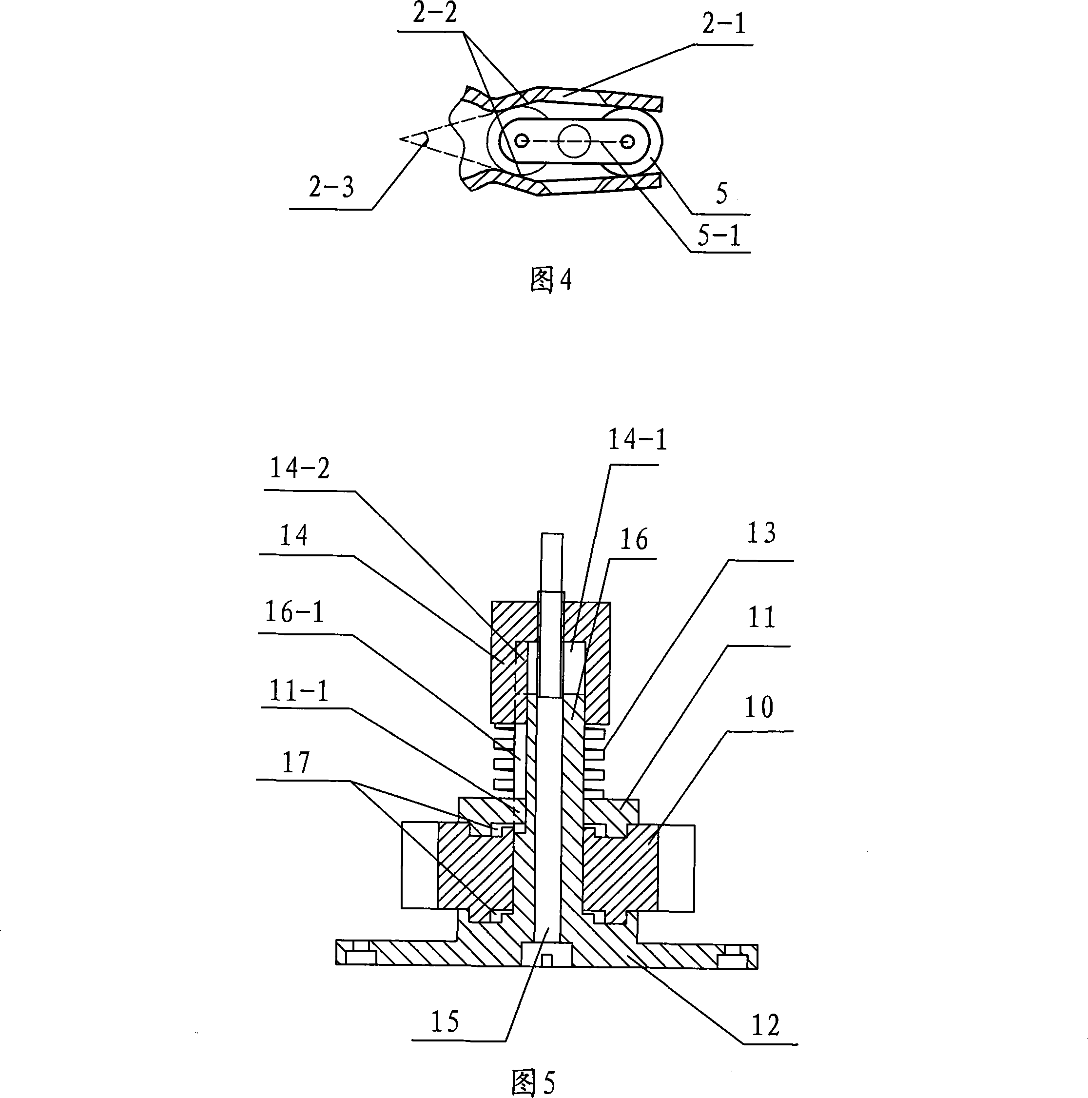
[0044] Refer to Figure 1, Figure 2, Figure 3, Figure 4 and Figure 5 for the embodiment of the upper shaft rotation control device of the free door. A free door upper shaft rotation control device includes a housing 1, a speed regulating damping device, an elastic splint 2, Rotate the connecting arm 3, rotate the upper shaft 4 and at least two rollers 5; the rollers are symmetrically installed on both sides of the rotating upper shaft with the rotating upper shaft as the center; the rotating upper shaft is rotated and fixed between the upper and lower side plates in the housing, One end of the rotating upper shaft extends out of the lower side plate of the housing; one end of the rotating connecting arm is fixed on the end of the rotating upper shaft protruding from the housing, and the center line of the two rollers is parallel to the rotating connecting arm; One end of the elastic splint is fixed, the other end of the elastic splint clamps the roller, and the speed regulating ...

Embodiment 2

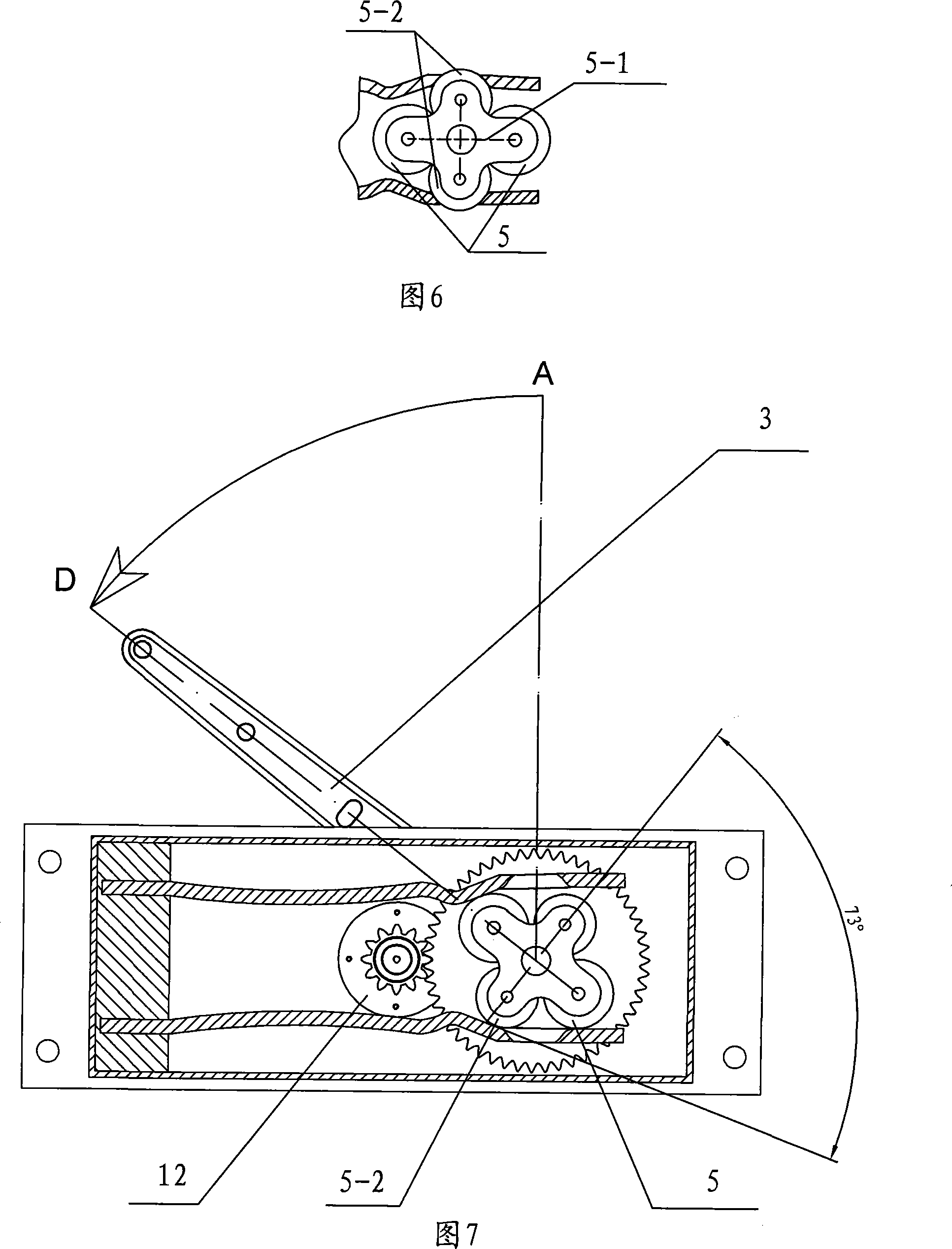
[0054] Referring to Figure 6, Figure 7 and Embodiment 1, in order to improve the stability of the door in the closed state and improve the wind resistance of the door when there is wind, two auxiliary rollers are added on the basis of Embodiment 1, that is, the free door There are four rollers in the upper shaft rotation control device. The diameters of the four rollers can be the same or different. The two rollers are divided into the first group and the second group. The two rollers of the first group are used to rotate the upper shaft. The two rollers of the second group are auxiliary rollers, which are symmetrically installed on the rollers of the first group. The two sides of the center connecting line, and the center distance of the two rollers of the second group is smaller than the center distance of the two rollers of the first group; Figure 6 shows the relationship between the elastic splint and the rollers when the upper shaft control device of the free door is in th...

Embodiment 3

[0056] Referring to Fig. 8, Fig. 9, 10 and Embodiment 1, the difference from Embodiment 1 is that the elastic splint is two rigid splints 18 and extension springs 19; one end of the two rigid splints is rotated and fixed by the splint shaft 20 in the housing , the splint shaft is fixed at one end of the housing through the fixed block 21 and the splint shaft bearing 22; the other ends of the two rigid splints clamp the two rollers of the rotation; the tension spring is arranged between the two rigid splints to pull the two rigid splints , the extension springs are arranged at the front and rear ends of the rollers clamped by the two rigid splints at the same time, and one or more can be arranged respectively according to the needs.

[0057] Fig. 8 and Fig. 9 show that when the door leaf of this embodiment is in the closed state, one end side of the two rigid splints clamps the two rollers at the same time through the action of the tension spring, and the center connection line ...


PUM


Abstract

The invention relates to a free gate controller used in construction, consisting of door leaves, a door frame, an upper shaft rotation control device, a lower shaft locating device and a shaft terminal locating block. The upper shaft rotation control device is fixed on the upper frame of the door frame; the lower shaft locating device is fixed on the lower frame of the door frame or the floor; the central rotating arm of the upper shaft rotation control device is connected fixedly with the upper architrave or the upper part of the upper gate folder of the door leaves; the bearing seat of the lower shaft locating device is fixed on the lower architrave or the lower part of the lower gate folder of the door leaves; the shaft terminal locating block contacts the rotary shaft of the rotary connecting arm of the upper shaft rotation control device and is fixed in the upper architrave or the upper part of the upper gate folder of the door leaves. Compared with the prior art, the invention is characterized by: 1. Time saving and laboring assembly; 2. Small volume, light weight, little consumption of the material, simple structure, low cost, easy manufacture, easy production; and characterized in that: 3. the invention changed that the lower shaft control device bears the weight of the gate in the prior art; the rotary device of the upper shaft is connected by bearing, thereby the stress and the wear of different working components are little, the service life is long and the reliability is high.

Description

technical field [0001] The invention relates to an automatic door closing device for building, in particular to a free door controller comprising a free door upper shaft rotation control device and a lower shaft positioning device. Background technique [0002] The floor spring that present known free door or the ground spring door generally adopts is mainly made up of parts such as floor spring, ground shaft arm, sky shaft latch, sky shaft bushing. Most of the floor springs are hydraulic cam structures, the manufacturing process is complicated, the volume is large, the material is many, and the cost is high. Because the hydraulic device is used, it affects its performance in low temperature climates; because the floor spring is set under the door leaf, it also works To carry the weight of the door body, the stress and wear of each component will be increased, so it is prone to failure, opening and closing failure, oil leakage and other problems, which will affect the servic...

Claims


Application Information

Patent Timeline
Patent Type & Authority Applications(China)
IPC IPC(8): E05F3/00E05F3/22E05F1/10
Inventor 初恒毅
Owner 初恒毅
Why Eureka
Try Eureka