Multipurpose heat exchange reaction device

A reaction device and a multi-purpose technology, applied in the field of multi-purpose heat exchange reaction devices, achieves the effects of uniform heat transfer, simple and convenient maintenance, and simplified control methods

Inactive Publication Date: 2008-06-18
李钢坤
View PDF0 Cites 6 Cited by
  • Summary
  • Abstract
  • Description
  • Claims
  • Application Information

AI Technical Summary

Problems solved by technology

[0003] In order to overcome the deficiencies of the existing known tube-and-tube heat exchange reaction devices, the present invention provides a tube-and-tube heat exchange reaction device that can be loaded with both granular catalysts and monolithic catalysts, and can have a built-in thermostat

Method used


Image

  • Multipurpose heat exchange reaction device
  • Multipurpose heat exchange reaction device

Examples


Embodiment 1

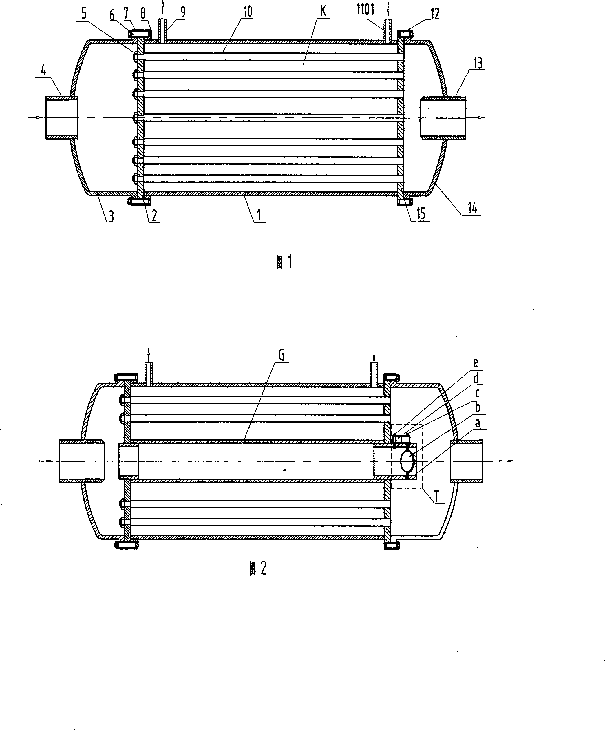
[0018] As shown in FIG. 1 , it includes a heat exchange reaction device consisting of a cylinder body 1 , a heat source fluid discharge end cover 14 , a heat source fluid inlet end cover 3 , several heat exchange tubes 10 , a bottom tube sheet 15 and an open tube sheet 2 . One end of the cylinder 1 is welded with a bottom tube plate 15, and the other open end has a cylinder flange 8, and the outer walls of the two ends of the cylinder 1 are respectively provided with a material inlet pipe 1101 and a material discharge pipe 9; the heat source fluid enters the open end of the end cover 3 There is a left end cover flange 7, and there is a heat source fluid inlet pipe 4 at the top; an open tube plate 2 is crimped between the left end cover flange 7 and the cylinder flange 8 through a screw 6; the heat source fluid discharge end cover 14 has a right end at the open end The cover flange 12 has a heat source fluid discharge pipe 13 on the top; the right end cover flange 12 is engaged ...

Embodiment 2

[0020] As shown in Figure 2, it consists of a cylinder body 1, a heat source fluid discharge end cover 14, a heat source fluid inlet end cover 3, a number of heat exchange tubes 10, a temperature-adjusting heat exchange tube G, a thermostat T, a bottom tube plate 15 and an opening A heat exchange reaction device composed of tube sheets 2. One end of the cylinder 1 is welded with a bottom tube plate 15, and the other open end has a cylinder flange 8, and the outer walls of the two ends of the cylinder 1 are respectively provided with a material inlet pipe 1101 and a material discharge pipe 9; the heat source fluid enters the open end of the end cover 3 There is a left end cover flange 7, and there is a heat source fluid inlet pipe 4 at the top; an open tube plate 2 is crimped between the left end cover flange 7 and the cylinder flange 8 through a screw 6; the heat source fluid discharge end cover 14 has a right end at the open end The cover flange 12 has a heat source fluid dis...

Embodiment 3

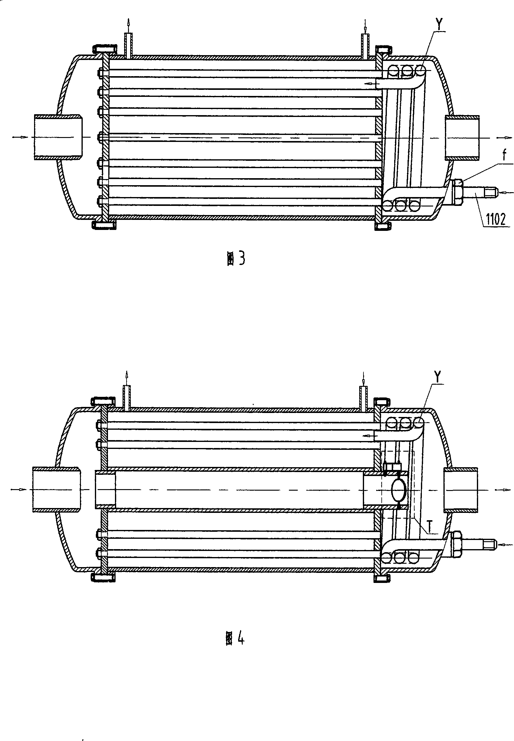
[0023] As shown in Figure 3, it includes a heat exchange system composed of a cylinder body 1, a heat source fluid discharge end cover 14, a heat source fluid inlet end cover 3, several heat exchange tubes 10, a preheater Y, a bottom tube plate 15 and an open tube plate 2. Reactor. One end of the cylinder 1 is welded with a bottom tube plate 15, and the other open end has a cylinder flange 8, and the outer walls of the two ends of the cylinder 1 are respectively provided with a material inlet pipe 1101 and a material discharge pipe 9; the heat source fluid enters the open end of the end cover 3 There is a left end cover flange 7, and there is a heat source fluid inlet pipe 4 at the top; an open tube plate 2 is crimped between the left end cover flange 7 and the cylinder flange 8 through a screw 6; the heat source fluid discharge end cover 14 has a right end at the open end The cover flange 12 has a heat source fluid discharge pipe 13 on the top; the right end cover flange 12 i...


PUM


Abstract

The invention discloses a multi-purposed heat exchange reaction apparatus consisting of a cylinder (1), a heat source fluid discharge end cover (14), a heat source fluid inlet end cover (3), a heat exchange tube (10), a thermostat (K), a pre-heater (Y), a bottom pipe board (15) and an opening pipe board (2). The apparatus has the advantage of convenience in removal because of the opening pipe board, so that the apparatus can carry integral catalyst and is applicable in occasions with vibration operating condition, etc.; with the thermostat built, the apparatus can not only save bypass pipelines for regulating temperature, but also simplify the control method. The invention has the advantages of compacted structure, even transfer of heat, convenience in compacted design and manufacturing, long service life of the catalyst, easiness and fastness in maintenance, and is in particular applicable to new technical projects, such as locomotive waste heat utilization, following hydrogen making, etc.

Description

Technical field [0001] The invention relates to a multipurpose heat exchange reaction device, which is suitable for various occasions with heat exchange and heat exchange reaction, and belongs to the field of chemical machinery, or especially the field of waste heat application of locomotive internal combustion engines. Background technique [0002] In the chemical machinery of the prior art, both ends of the heat exchange tubes inside the tube-and-tube heat exchange reaction device are welded or expanded on the tube sheet, and the tubes and the tube sheet are in a fixed state. The biggest shortcoming of this tube-and-tube heat exchange reaction device is that in the cavity between the outer wall of the tube and the inner wall of the cylinder of the reaction device, only granular catalysts can be loaded, and monolithic catalysts cannot be used. If this device is applied to occasions with severe vibration conditions, such as waste heat utilization of locomotive engines, etc.,...

Claims


Application Information

Patent Timeline
Patent Type & Authority Applications(China)
IPC IPC(8): F28D7/10F28D7/16
Inventor 李钢坤
Owner 李钢坤
Why Eureka
Try Eureka