
Method for locating parameter type fault of analogue integrated circuit

A technology of integrated circuits and positioning methods, which is applied in analog circuit testing, electronic circuit testing, etc., and can solve the problems of low efficiency of multi-parameter fault location, difficult diagnosis and automation, etc.

Inactive Publication Date: 2008-06-18
UNIV OF ELECTRONICS SCI & TECH OF CHINA
View PDF0 Cites 22 Cited by
  • Summary
  • Abstract
  • Description
  • Claims
  • Application Information

AI Technical Summary

Problems solved by technology

These methods are not efficient for fault location of analog integrated circuits, especially for multi-parameter fault location, and there are defects that it is not easy to realize automatic diagnosis

Method used


Image

  • Method for locating parameter type fault of analogue integrated circuit
  • Method for locating parameter type fault of analogue integrated circuit
  • Method for locating parameter type fault of analogue integrated circuit

Examples


Embodiment 1

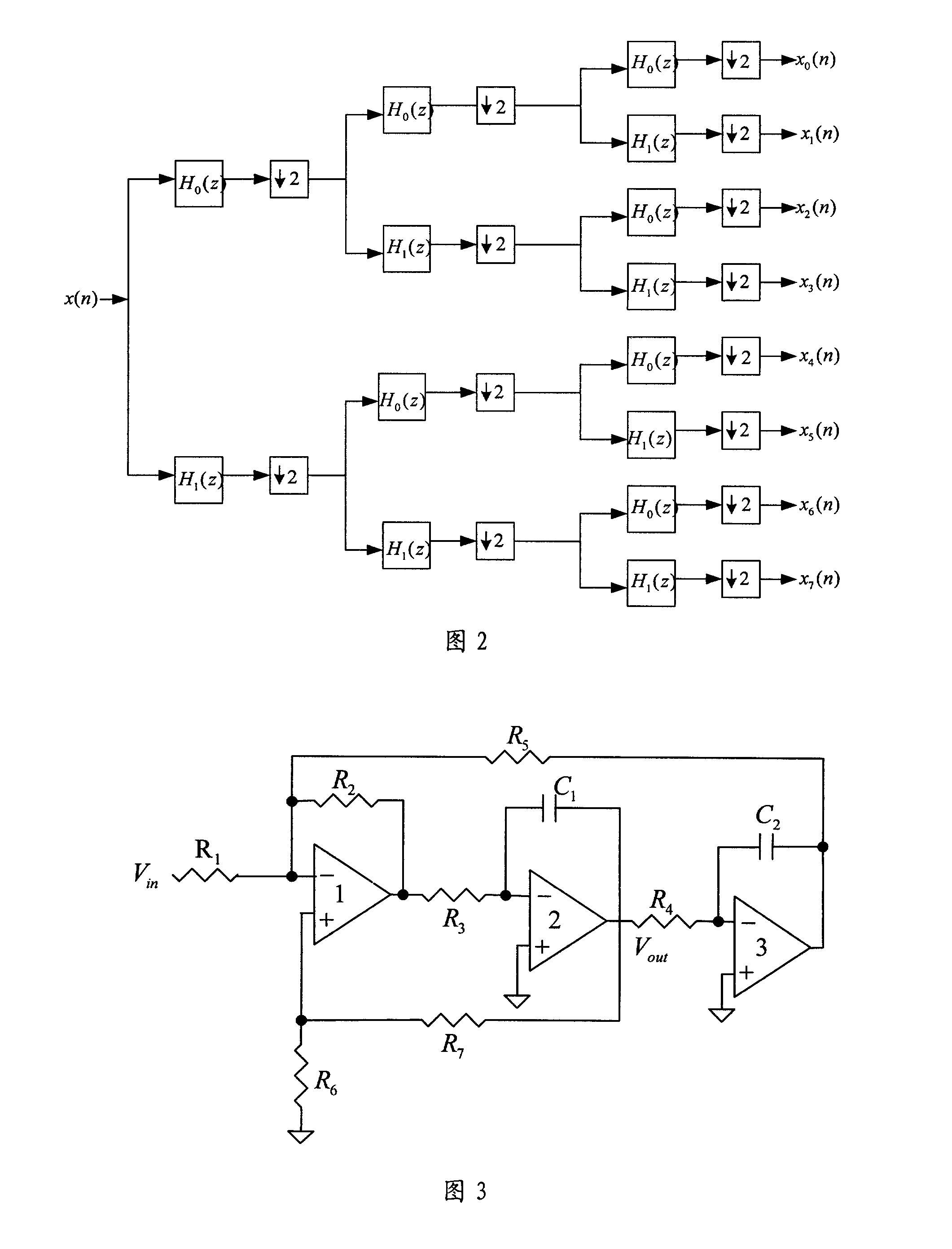
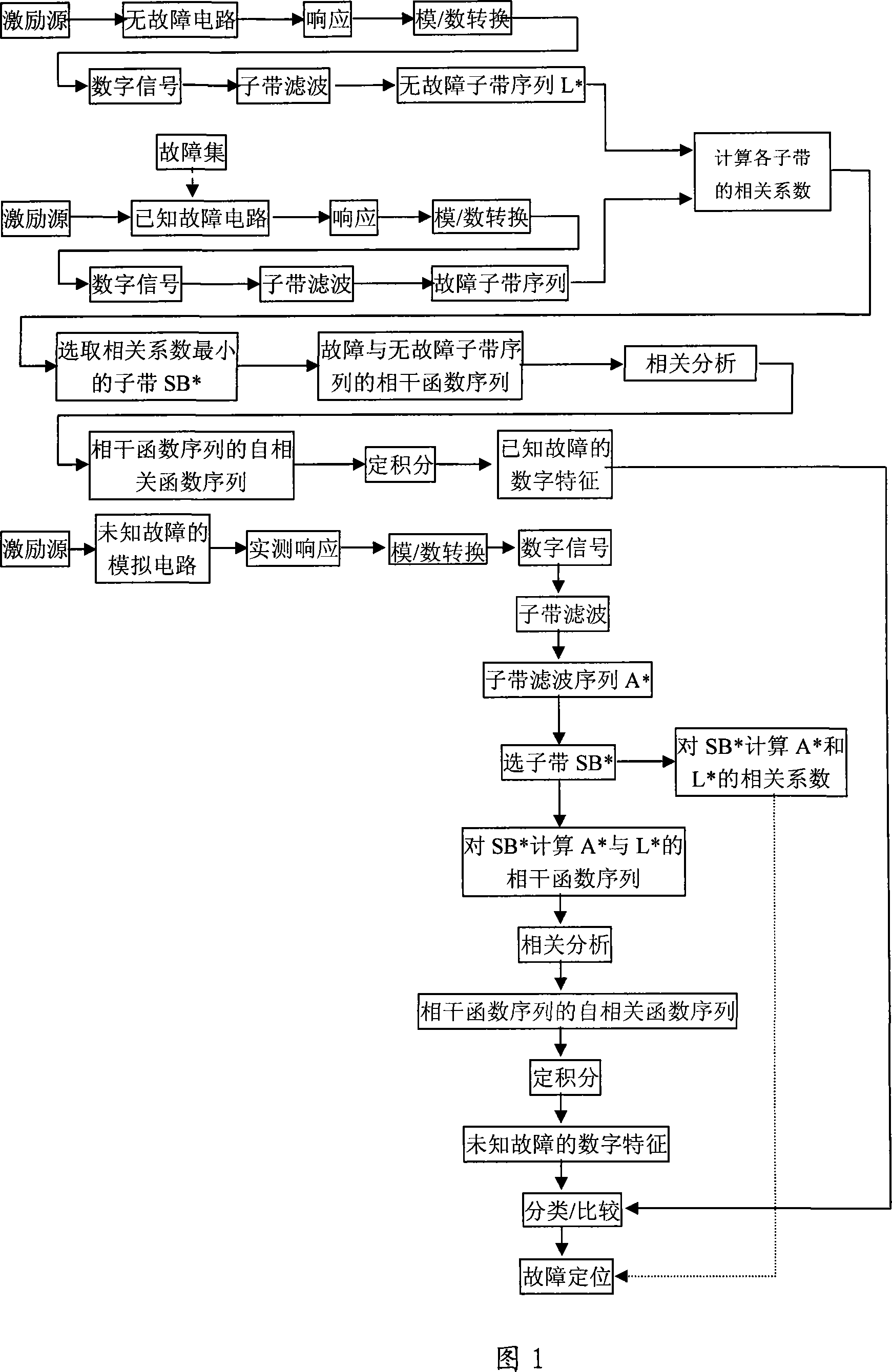
[0052] As shown in Figure 1, Figure 2, Figure 3, Figure 4, Figure 5, Figure 6, and Figure 7. The state variable filter in the international standard circuit is selected to test the method for locating the parametric fault of the simulated integrated circuit of the present invention. Device parameters for the state variable filter: R 1 = R 3 = R 4 = R 5 = R 6 = R 7 = 10KΩ, R 2 = 1KΩ, C 1 =C 2 =20nF. Two parametric faults are: R fault, resistance R 1 Drift 5%; C failure, capacitance C 1 Drift 6%.

[0053] (1) The excitation source acts on the measured non-fault state variable filter to provide a test excitation signal for the measured non-fault state variable filter, and the test excitation signal is a sine wave signal with a frequency of 1.0KHz and an amplitude of 5.0V; The response of the measured non-fault state variable filter is transformed into a non-fault digital signal through analog-to-digital conversion; the Haar wavelet filter bank with a pyramid structure...

Embodiment 2

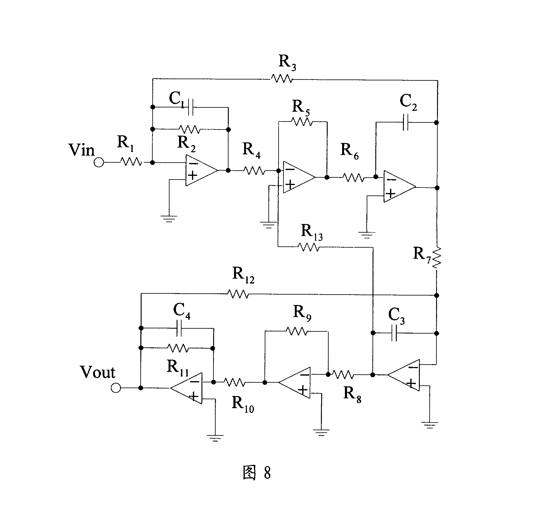
[0069] As shown in Figure 1, Figure 2, and Figure 8. The same places as in Embodiment 1 will not be described again, the difference is that: the leapfrog filter in the international standard circuit is selected to test the method for locating the parametric fault of the analog integrated circuit of the present invention. The device parameters of the leapfrog filter: all resistors R 1 to R 13 The resistance value is 10KΩ, the capacitance C 1 =C 4 = 0.01μF, C 2 =C 3 = 0.02 μF. Experiments were carried out on 10 multi-parameter fault combinations, and the results are shown in the table below.

[0070] Fault serial number

#

parametric failure

wavelet subband

#

correlation coefficient

Autocorrelation of sequence of coherence functions

Function sequence definite integral value

1

(C 1 &C 2 )+5%

7

-0.0013

389.6140

2

(C 1 &C 3 )+5%

8

-0.0721

583.7254

3 ...

Embodiment 3

[0075] The parts that are the same as those in Embodiment 1 will not be described again, the difference is that the fault-free subband sequence obtained in step (1) is obtained through theoretical calculation. The fault subband sequence obtained in step (2) is obtained through theoretical calculation.


PUM


Abstract

The invention discloses a location method of the parameter type fault of the analog integrated circuit. The invention carries out the polyphase filter bank for the measured analog integrated circuit, then calculates the cohere function sequence which corresponds to the faultless sub band sequence for the fault polyphase filter bank sequence in the sub band of the highest fault resolution, and obtains the autocorrelation function sequence of the cohere function sequence, and takes the definite integral answers of the autocorrelation function sequence of the cohere function as the digital characteristic of the fault to realize the fault location. By comparing to the exist technology, the invention can realize the location of the parameter type fault of the analog integrated circuit, reach high accuracy of fault diagnosis, high fault resolution and high fault coverage, realize the multi-parameter type fault location, and easily realize the automation of the fault diagnosis by the digitized fault characteristic with the obvious difference.

Description

technical field [0001] The invention belongs to the field of fault diagnosis of integrated circuits, in particular to a method for locating parametric faults of simulated integrated circuits. Background technique [0002] Analog integrated circuits can cause component parameters to deviate (drift) from their nominal values ​​due to various reasons. The parameter deviation can cause circuit performance degradation. If the parameter deviation exceeds the tolerance range, it will become a parametric fault of the analog integrated circuit. At this time, the circuit’s Although the topology has not changed, it will cause severe degradation or even failure of the circuit performance. [0003] At present, domestic and foreign researches on parametric fault diagnosis of analog integrated circuits are very active. Typical fault diagnosis methods include parametric fault detection methods based on circuit transfer function coefficients and test methods based on subband filtering. The...

Claims


Application Information

Patent Timeline
Patent Type & Authority Applications(China)
IPC IPC(8): G01R31/28G01R31/316
Inventor 谢永乐李西峰
Owner UNIV OF ELECTRONICS SCI & TECH OF CHINA
Learn More