Magnetic sensor and manufacturing method thereof
A manufacturing method and magnetic sensor technology, applied in the manufacture/processing of electromagnetic devices, instruments, and measuring magnetic variables, etc., can solve the problems of complicated sensor production, high sensor price, trouble, etc.
- Summary
- Abstract
- Description
- Claims
- Application Information
AI Technical Summary
Problems solved by technology
Method used
Image

Examples
Embodiment 1
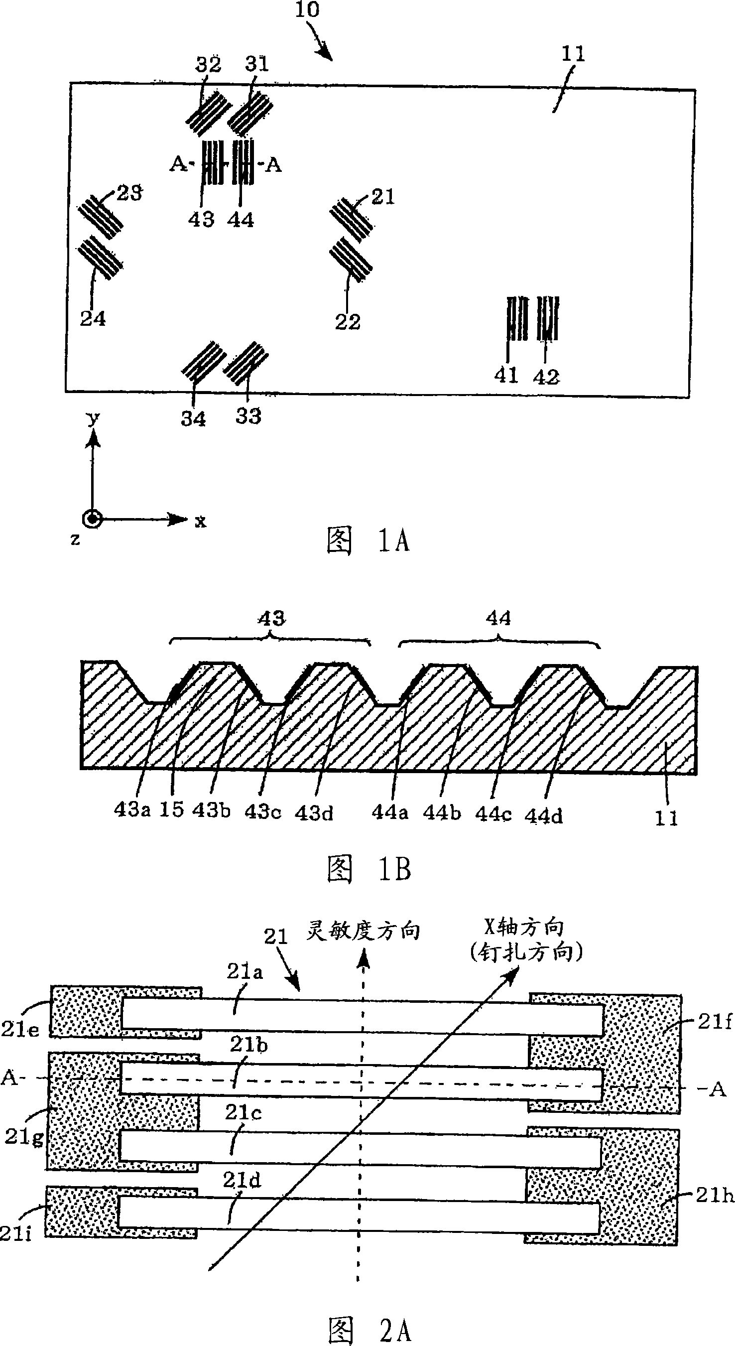
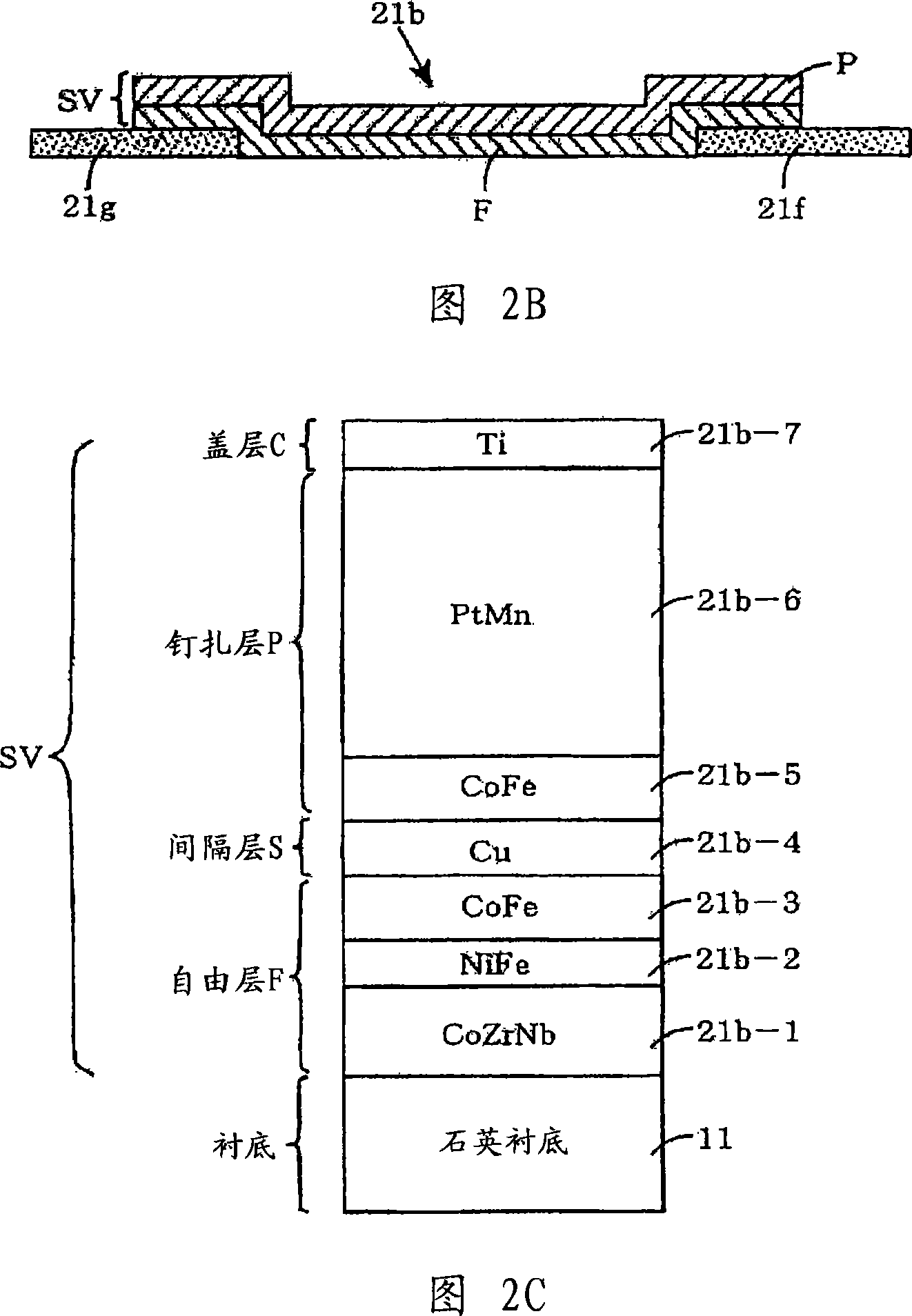
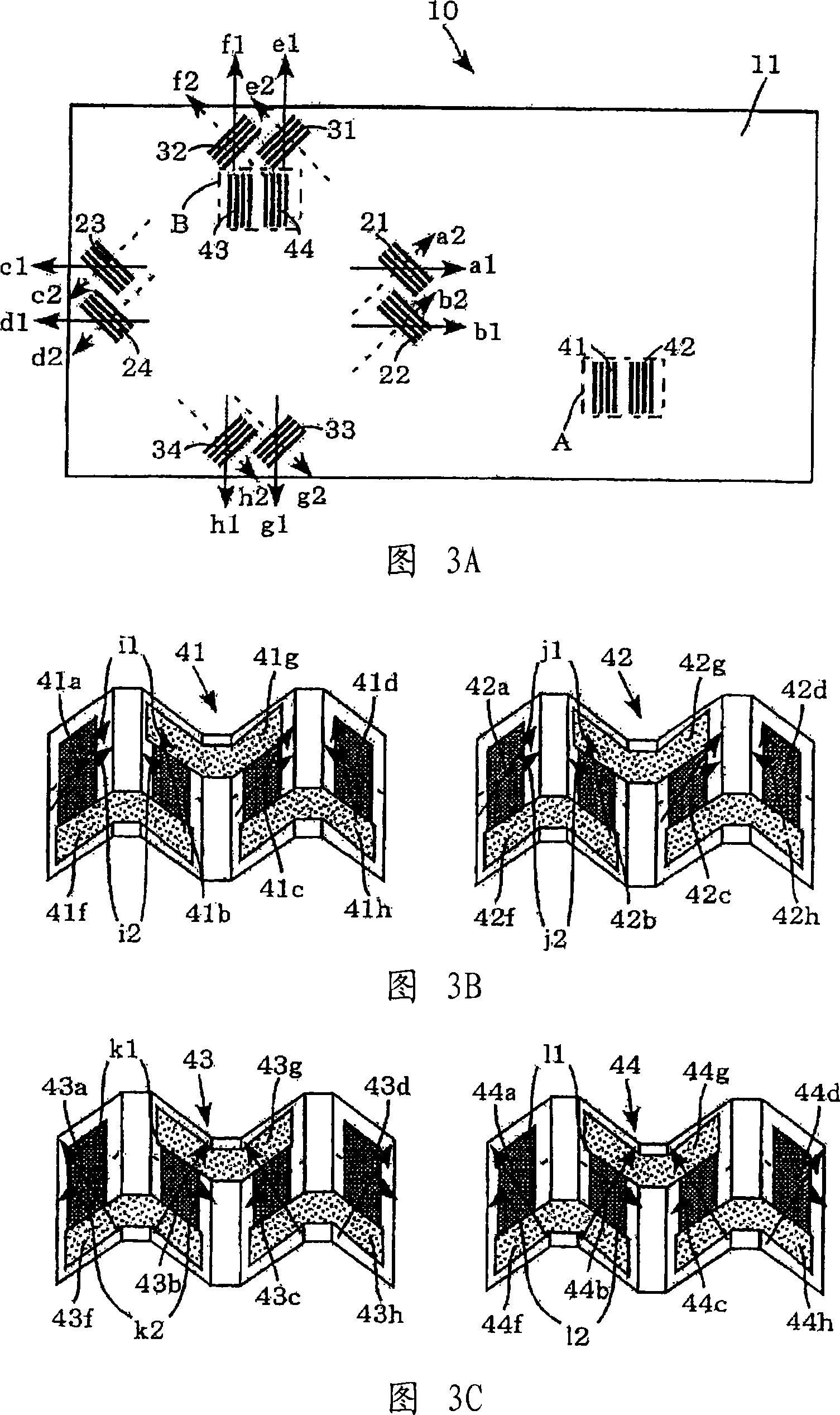
[0201] First, the three-axis magnetic sensor of Embodiment 1 will be described with reference to FIGS. 1A to 15C .
[0202] The three-axis magnetic sensor 10 of Embodiment 1, as shown in FIGS. 1A and 1B , has a rectangular shape (here, the short side ( The ratio (aspect ratio) of the longitudinal side) to the long side (transverse side) is 1:2, and the side extending along the X-axis is the long side, and the side extending along the Y-axis is the short side), and is configured with A substrate 11 made of quartz or silicon with a relatively small thickness in the Z-axis direction perpendicular to the X-axis and the Y-axis. On the substrate 11, a total of twelve GMR elements consisting of four X-axis GMR elements 21-24, Y-axis GMR elements 31-34, and Z-axis GMR elements 41-44 are formed, and a total of There are twelve pads (not shown in the figure) and connection lines (not shown in the figure) connecting each pad to each element. Moreover, in this substrate 11, LSI (Large S...
Embodiment 2
[0252] Next, the three-axis magnetic sensor of the second embodiment will be described with reference to FIGS. 17A to 20C.
[0253] The three-axis magnetic sensor 60 of Embodiment 2, as shown in FIGS. 17A and 17B , has a rectangular shape with sides extending in the X-axis direction and the Y-axis direction orthogonal to each other in plan view (here, the short sides (longitudinal sides) ) to the long side (lateral side) ratio (aspect ratio) is 1:1.5, and the side extending along the X-axis is the long side, and the side extending along the Y-axis is the short side), and is configured with The substrate 61 made of quartz or silicon has a relatively small thickness in the direction of the Z axis perpendicular to the Y axis. With the substrate 61 having such a structure, further miniaturization than that of the three-axis magnetic sensor of Embodiment 1 can be achieved.
[0254] On this substrate 61, a total of twelve GMR elements including four X-axis GMR elements 61a to 61d, ...
Embodiment 3
[0280] Next, the three-axis magnetic sensor of the third embodiment will be described with reference to FIGS. 21A to 24B .
[0281] The three-axis magnetic sensor 70 of Embodiment 3, as shown in FIGS. 21A and 21B , has a square shape (that is, the size is about half of the substrate 11 in the above-mentioned Embodiment 1), and has X axes orthogonal to each other in a plan view. The side extending in the X-axis and the Y-axis direction, and a substrate 71 made of a quartz substrate or silicon having a relatively small thickness in the Z-axis direction perpendicular to the X-axis and the Y-axis is arranged. With the substrate 71 having such a structure, it is possible to achieve further miniaturization than the three-axis magnetic sensor of the first embodiment and the three-axis magnetic sensor of the second embodiment.
[0282] A total of ten GMR elements including four X-axis GMR elements 71a to 71d, Y-axis GMR elements 71e to 71h, and two Z-axis GMR elements 71i and 71j are ...
PUM
 Abstract
Description
Claims
Application Information
 - Generate Ideas
- Intellectual Property
- Life Sciences
- Materials
- Tech Scout
- Unparalleled Data Quality
- Higher Quality Content
- 60% Fewer Hallucinations
Browse by: Latest US Patents, China's latest patents, Technical Efficacy Thesaurus, Application Domain, Technology Topic, Popular Technical Reports.
© 2025 PatSnap. All rights reserved.Legal|Privacy policy|Modern Slavery Act Transparency Statement|Sitemap|About US| Contact US: help@patsnap.com