Automatic toothbrush driven by air press and fluid pressure

A hydraulic and pneumatic technology, applied in the field of automatic toothbrushes, can solve the problems of cumbersome tooth cleaning methods, too many cleaning steps, and incomplete cleaning, and achieve the effects of low cost, convenient use, and simple structure

Active Publication Date: 2008-06-25
绍兴市爱牙牙科技有限公司
1 Cites 2 Cited by

AI-Extracted Technical Summary

Problems solved by technology

[0007] The present invention mainly solves the technical problems of cumbersome tooth cleaning methods in the prior art, too many cleaning steps, incomplete cleaning, etc.; it provides a tooth cleani...

Abstract

The invention relates an automatic toothbrush belonging to the hygiene field of oral cavity or teeth, in particular to an automatic toothbrush driven by air pressure or hydraulic pressure. The invention essentially solves the technical issues of trivial method for cleaning the teeth, overabundant cleaning steps and incomplete cleaning and so on in the prior art; the invention provides an automatic toothbrush driven by tap water with simple structure, combination of diversified functions, high cleaning efficiency and complete cleaning. The invention relates an automatic toothbrush belonging to the hygiene field of oral cavity or teeth, in particular to an automatic toothbrush driven by air pressure or hydraulic pressure. The invention essentially solves the technical issues of trivial method for cleaning the teeth, overabundant cleaning steps and incomplete cleaning and so on in the prior art; the invention provides an automatic toothbrush driven by tap water with simple structure, combination of diversified functions, high cleaning efficiency and complete cleaning.

Application Domain

Brush bodiesBristle carriers

Technology Topic

Pneumatic pressureEngineering +5

Image

  • Automatic toothbrush driven by air press and fluid pressure
  • Automatic toothbrush driven by air press and fluid pressure
  • Automatic toothbrush driven by air press and fluid pressure

Examples

  • Experimental program(1)

Example Embodiment

[0027] Example 1:
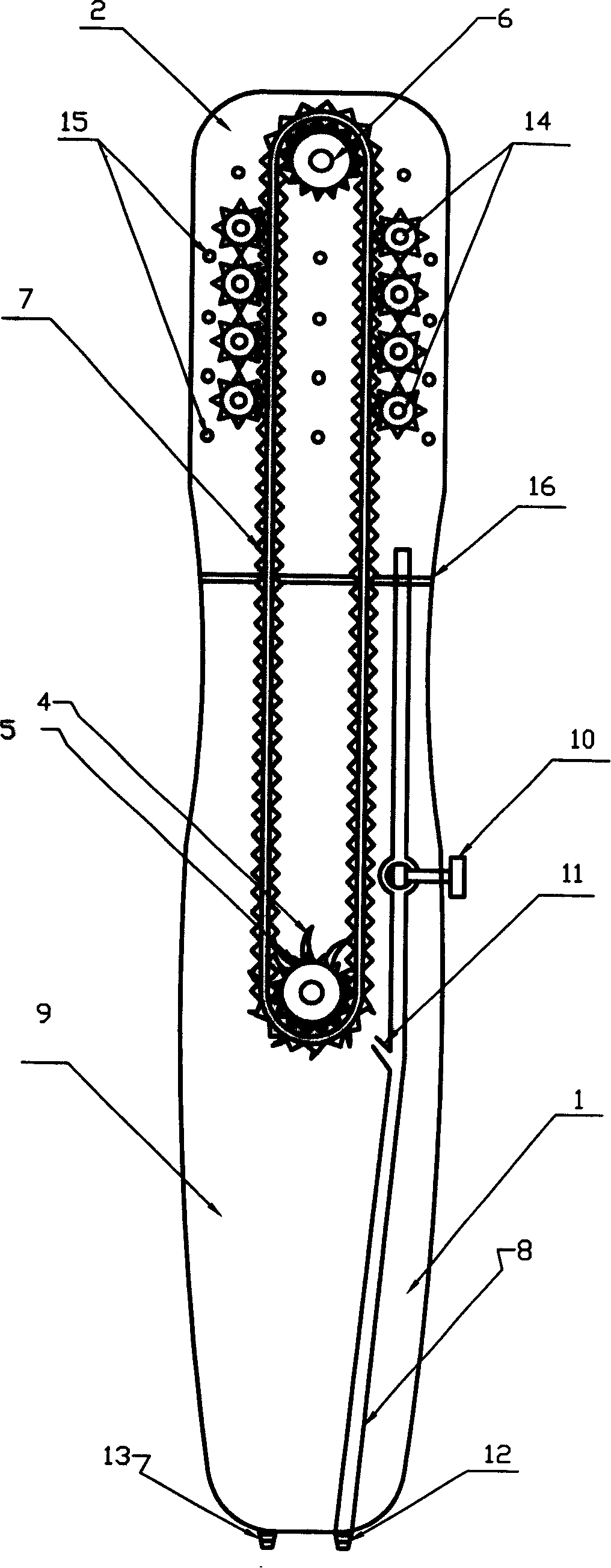
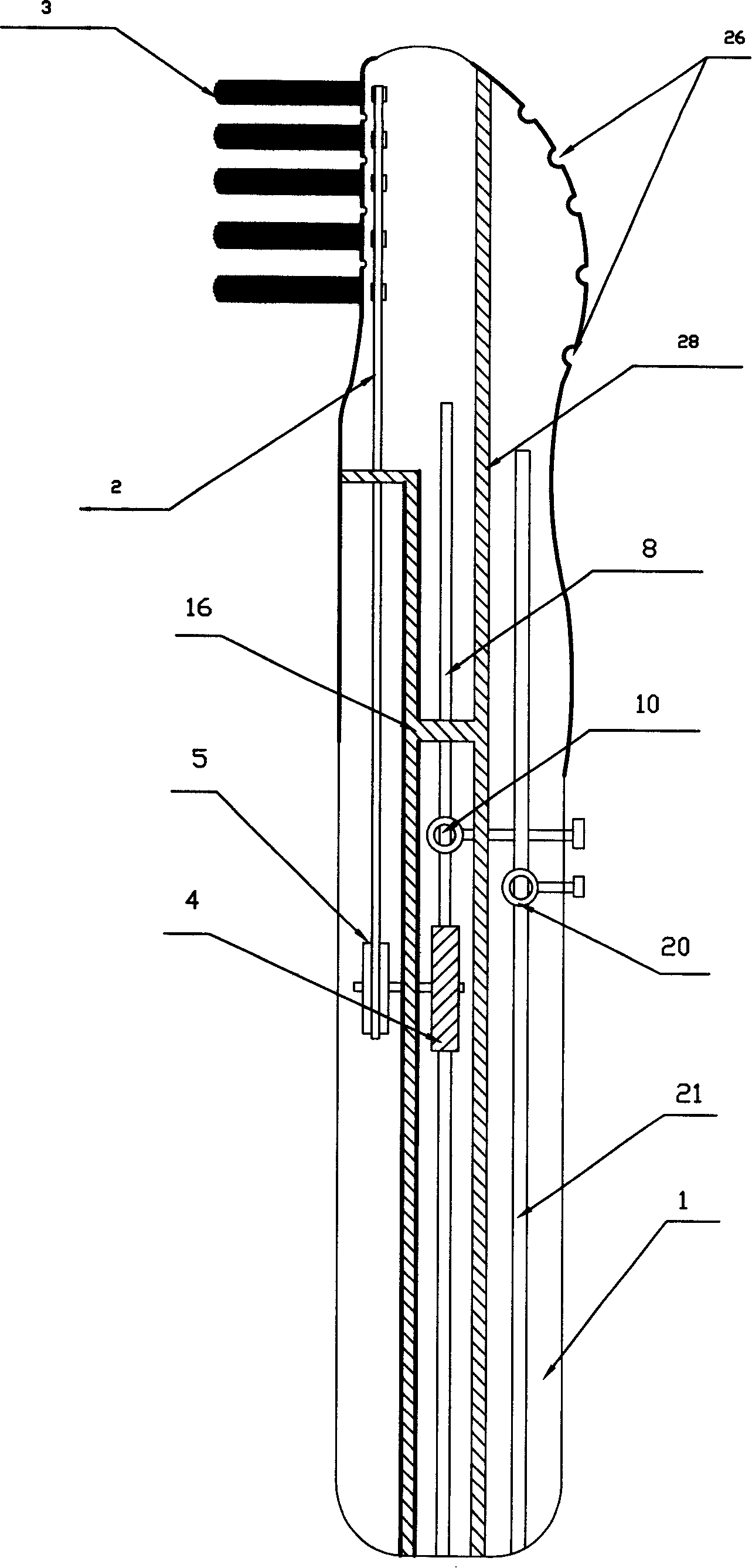
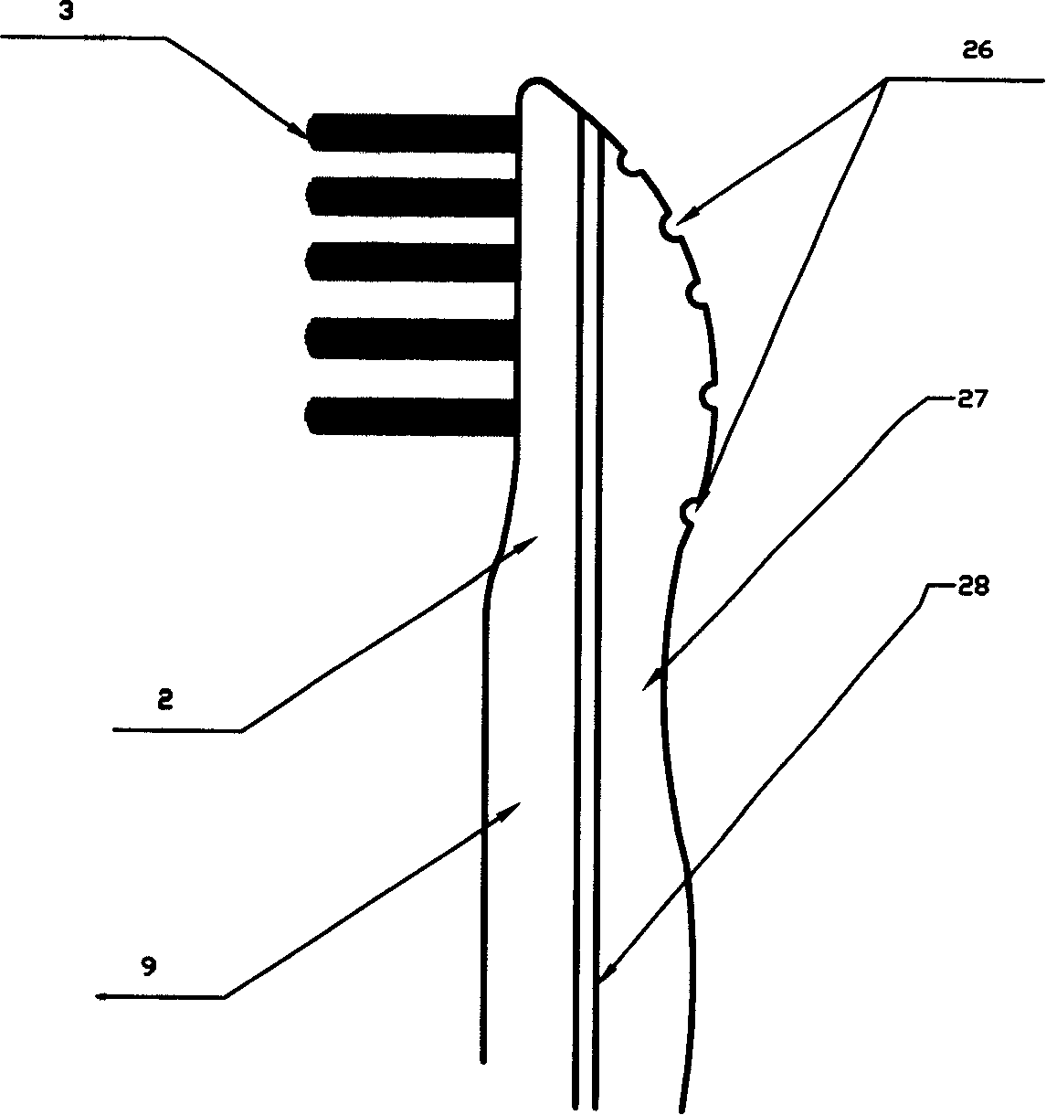
[0028] Such as figure 1 , figure 2 , Figure 5 7. As shown in Figure 7, the automatic toothbrush consists of a toothbrush body 1, a toothbrush head 2 and bristles 3. A turbine 4 is installed in the toothbrush body 1, the turbine shaft is fixed on the toothbrush body 1, and the turbine 4 is installed in the cavity 9; The top of the toothbrush head 2 is provided with a passive gear 6, and a transmission belt 7 is provided between the driving gear 5 and the passive gear 6. The transmission belt 7 can be designed as a double-sided triangular toothed transmission belt 20, or it can be provided with a hole punched The perforated transmission belt 21 has a tooth pitch corresponding to the teeth of the main gear 5, the driven gear 6 and the multiple pinion gears 14; there are also eight pinion gears 14 in the toothbrush head 2, which are located on the transmission belt 7. On both sides, the bristle holder 17 is connected with the plurality of pinions 14; the toothbrush body 1 is also provided with a water inlet pipe 8 and a cavity 9 in the water inlet pipe 8 on the upper part of the turbine 4 There is a water inlet and outlet switch 10, and its lower part is located on the side of the turbine 4 with a water spray nozzle 11, the direction is aligned with the blades of the turbine 4, the turbine 4 and the water spray nozzle 11 are sealed by a water barrier 16 and the water outlet cavity 9 Separate; the bristles 3 are connected with the bristles holder 17 by the lock 18, and the bristles holder 17 is integrated with the pinion 14 and the pinion shaft 19; the lower end of the water inlet pipe 8 is provided with a serrated water inlet 12, the cavity The lower end of 9 is provided with a serrated water outlet 13; there are ten water outlets 15 on one side of the bristles of the brush head; the driving gear 5, the driven gear 6, and the cavity 9 are separated by a water barrier 16; the water inlet switch 10 There is a vertical circular hole inside, which is usually closed. When you want to rinse your mouth, rotate it at a 90-degree angle to communicate with the water inlet pipe 8. The toothbrush head 2 is equipped with a toothbrush head negative pressure cavity wall 28, and the back is isolated to form a water absorbent In the cavity 27, there is a negative pressure suction tube 21 in the suction chamber 27. One end of the negative pressure suction tube 21 is opened in the suction chamber 27 and one end is opened on the toothbrush body 1. The negative pressure suction tube 21 is provided with a switch 20, and the toothbrush head 2 is drilled with Several small holes form the water suction hole 26; the serrated water inlet 12 is connected to the soft water pipe so as to directly communicate with the tap water pipe. The water pressure range is 0.1-0.5Mpa, and the flow rate can be greater than 8L/min; the rotation speed of the turbine 4 is 0.5-5.0 million revolutions per minute.
[0029] When in use: connect the water pipe with the inlet pipe, connect the water outlet with the outlet pipe, turn on the tap, and the water flow enters the cavity through the inlet pipe, driving the turbine to rotate, and the water flows out of the cavity along the outlet pipe; the turbine rotates at high speed to make the bristles The support moves in a circle along the turbine shaft. Because the bristles are fixed on the bristle support, the bristles move in the same trajectory as the bristle support, and the bristles can play the role of cleaning the teeth; the multiple openings on the brush head surface can shoot water out to wash away The role of teeth; the negative pressure suction tube generates suction under the action of negative pressure, and sucks the sewage in the oral cavity through the suction hole on the back of the brush head.

PUM

no PUM

Description & Claims & Application Information

We can also present the details of the Description, Claims and Application information to help users get a comprehensive understanding of the technical details of the patent, such as background art, summary of invention, brief description of drawings, description of embodiments, and other original content. On the other hand, users can also determine the specific scope of protection of the technology through the list of claims; as well as understand the changes in the life cycle of the technology with the presentation of the patent timeline. Login to view more.

Similar technology patents

Medical foldable bedside cabinet

Owner:苏州优点优唯医疗科技有限公司

Magnetic resonance imaging method of magnetization transfer and level choose inversion recovery combined pre-pulse

ActiveCN104856677AThe method steps are simplereasonable design
Owner:THE FIRST AFFILIATED HOSPITAL OF MEDICAL COLLEGE OF XIAN JIAOTONG UNIV

Steel pipe roundness measuring instrument

Owner:中能达(厦门)自动化科技有限公司

Classification and recommendation of technical efficacy words

  • Simple structure
  • reasonable design

Method for coal and gas outburst simulation experiment

Owner:CHINA COAL TECH ENG GRP CHONGQING RES INST

Embedding accuracy control construction method for embedded part of overlong equipment foundation platform

InactiveCN102134879Areasonable designSimple construction steps
Owner:SCEGC NO 6 CONSTR ENG GRP CO LTD

Frequency hopping communication anti-interference method based on cognitive radio

ActiveCN103441779AImprove anti-jamming communication abilityreasonable design
Owner:深圳市研谱科技有限公司
Why Eureka
Try Eureka