Double sealing high pressure needle valve

A high-pressure needle and double-sealing technology, which is applied in the direction of lift valves, valve devices, engine components, etc., to achieve the effects of long service life, good sealing performance and good sealing effect

Inactive Publication Date: 2008-06-25
金进星
View PDF0 Cites 9 Cited by
  • Summary
  • Abstract
  • Description
  • Claims
  • Application Information

AI Technical Summary

Problems solved by technology

The double-seal high-pressure needle valve can well solve the problem of "running, popping, dripping, and leaking" of the high-pressure needle valve seal

Method used


Image

  • Double sealing high pressure needle valve

Examples


Embodiment Construction

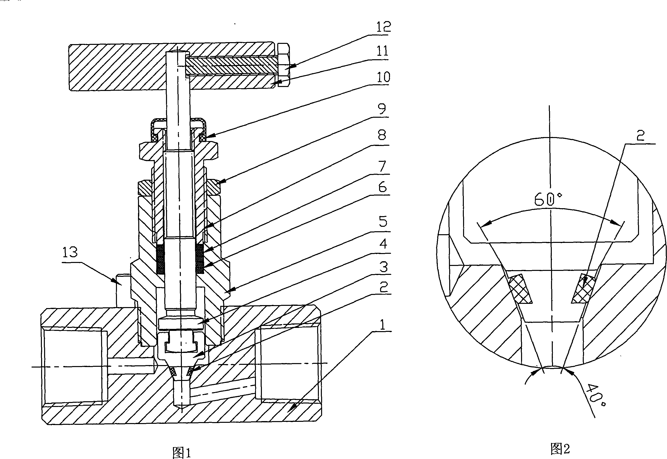
[0011] As shown in the accompanying drawings, the double-sealed high-pressure sealing needle valve of the present invention mainly includes a valve body 1, a valve tip 3, a valve stem 4, an upper valve cover 5, and a handle 11. The valve tip 3 and the valve stem 4 are formed by a T-shaped groove No swing hitch. The valve tip seal includes a hard seal part and a soft seal part. The taper of the hard seal part is larger than the taper of the soft seal part, and the taper of the hard seal part is consistent with the taper of the upper part of the valve body sealing port, generally 60°±1°, which forms a sealing line in sealing contact with the upper line of the valve body sealing port; the soft seal The taper surface of the upper part is consistent with the cone surface of the lower part of the valve body sealing port, generally 40°±1°, machined into a trapezoidal groove and assembled with a fluororubber O-ring 2, the fluororubber O-ring 2 is higher than the valve tip 3 The cone ...


PUM


Abstract

The invention relates to a dual seal high pressure needle valve. A valve tip seal comprises a hard seal part and a soft seal part having different tapers, wherein the hard seal part is in line seal contact with the upper conical surface of a valve body seal opening, the soft seal part is in seal contact with the lower conical surface of the valve body seal opening, the valve tip and a valve stem are hitched together without revolution through a T-shaped slot. The seal structure adopts the dual seal of line hard seal and conical surface soft seal, and the hitching without revolution between the valve tip and the valve stem via the T-shaped slot. When a seal surface wears, the lower conical surface of the seal opening and the soft seal can compensate to prevent medium leakage, thereby overcoming the problems of 'running, emitting, dripping and leaking' lying in the prior single hard soft seat needle valve. The invention which has the advantages of good sealing performance and long service life is applicable to the instrument pipeline cutoff, discharging and sampling technical fields in industries like oil, chemical engineering, electric power, metallurgy, food, etc.

Description

technical field [0001] The invention relates to a high-pressure needle valve, in particular to a double-seal high-pressure needle valve. Background technique [0002] Existing high-pressure needle valve seals rely on metal-to-metal or metal-to-nonmetal to produce a seal. The sealing of this structure has high requirements on the hardness of the valve tip, and it cannot meet the needs of mixed gas and media containing abrasives, which in turn leads to the phenomenon of "running, popping, dripping, and leaking". Especially the integrated structure of the valve stem, due to the medium wear of the rotation and abrasives, the line seal generated when it is closed becomes wider and wider, and long-term use will cause internal leakage of the needle valve. Over the years, in order to solve the problem of leakage of the closed sealing part of the needle valve under high pressure, various methods have been adopted at home and abroad, such as changing the angle of the cone, selecting ...

Claims


Application Information

Patent Timeline
Patent Type & Authority Applications(China)
IPC IPC(8): F16K1/00F16K1/38F16K1/48
Inventor 李国标金进星
Owner 金进星
Why Eureka
Try Eureka