Test device for rain sensor and method

A rain sensor and inspection equipment technology, applied in rainfall/precipitation meters, instruments, measuring devices, etc., can solve the problems of easy failure, poor repeatability, and easy contamination of silicon punches

Inactive Publication Date: 2008-06-25
ROBERT BOSCH GMBH
View PDF0 Cites 3 Cited by
  • Summary
  • Abstract
  • Description
  • Claims
  • Application Information

AI Technical Summary

Problems solved by technology

Such systems are implemented mechanically and are prone to failure due to this
In addition, the silicon punches that move over the sensitive surface of the test disc are prone to soiling or rest on different planes on the test disc due to fluctuations in the contact force, so that in this type of functional test, it is not possible to select from multiple Reproducible results in rain sensors
[0004] However, this mechanical method of simulating the light emission on the rain sensor has the disadvantage that the light emission parameters cannot be kept constant in a simple manner because, for example, when using silicon punches, these parameters are not related to the parameters or the compaction of the silicon punch. force, the cleanliness of the disk surface, and other mechanical influences of the device
Therefore, the repeatability of this type of mechanical method is poor, which makes it difficult to determine the degree of sensitivity of the rain sensor and the functional increase of the sensitive area with sufficient accuracy.

Method used


Image

  • Test device for rain sensor and method

Examples


Embodiment Construction

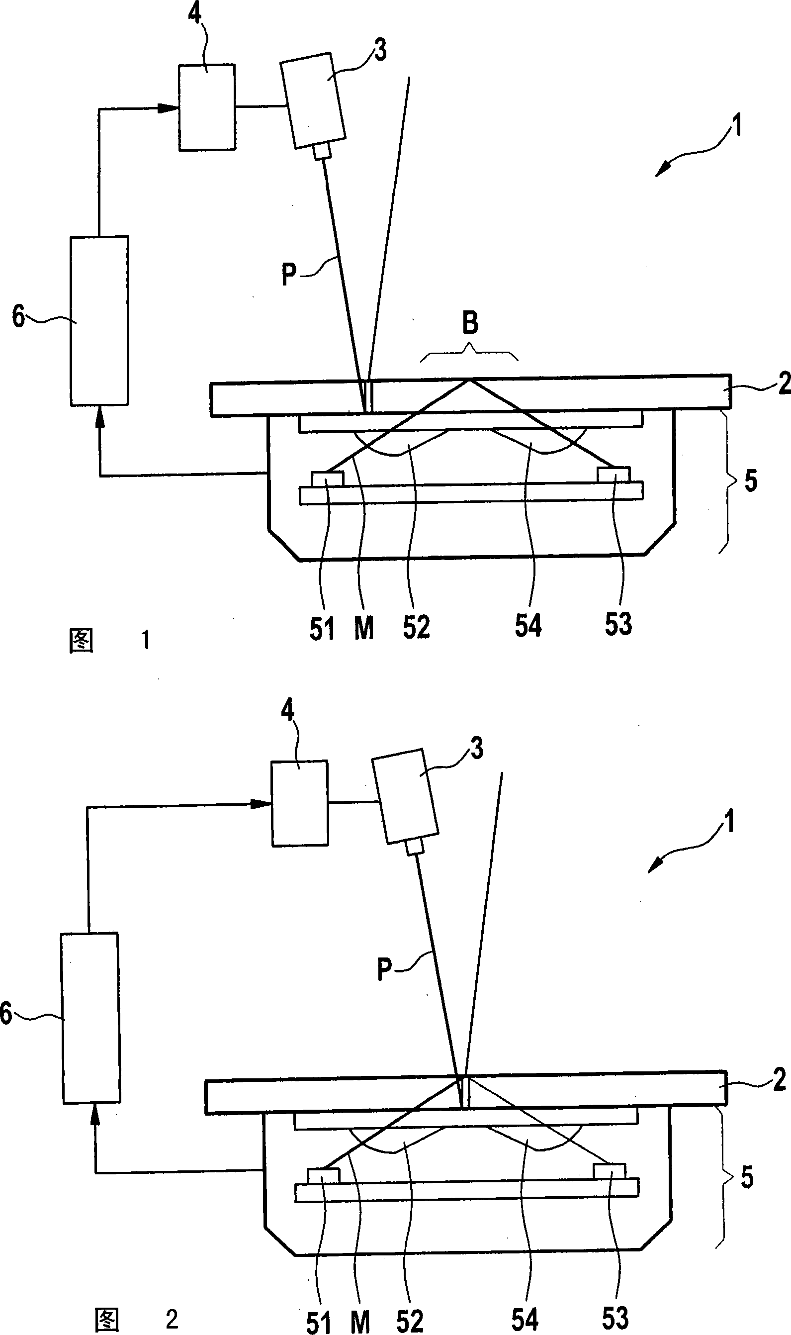
[0021] Embodiments of the invention make use of the idea that, for the detection of an optoelectronic rain sensor, the transmission properties of the test disc on which the rain sensor to be detected is placed are selectively attenuated. The measuring beam detected by the receiver of the rain sensor is thus attenuated when passing through the test disk, as is the case when raindrops hit the sensitive surface of the test disk. According to the concept of the invention, the change in transmission is achieved by the fact that the test disk is designed to be interchromatic and that the change in transmission is achieved by targeted irradiation of the detection beam.

[0022] An embodiment of the invention is shown in FIGS. 1 and 2 . The figures show a test system 1 with a test device. The testing device includes a testing disk 2 , a positionable testing light source 3 and a positioning device 4 . In order to test the rain sensor 5, the rain sensor is placed on the test disk 2 in...


PUM


Abstract

The invention relates to a detection device for detecting a photoelectric sensor (5), comprising a detection disk (2) having the phototropism property, wherein, a rain sensor (5) to be detected can be arranged on the detection disk for detection; and a detection light source (3) which is used for aligning the detection light beam (P) with at least one region which is defined by the rain sensor (5) inside the sensitive surface (8) arranged on the detection disk (2), thereby changing the transmission property of the detection disk (2) in the region.

Description

technical field [0001] The invention relates to a testing device with which the function of an optoelectronic rain sensor can be checked. Furthermore, the invention relates to a method for checking the function of an optoelectronic rain sensor. Background technique [0002] The rain sensors used in automobiles today are based on the principle of optoelectronic function. Such rain sensors have light sources, such as laser diodes or infrared light-emitting diodes. It emits a light beam which, for example, strikes the windshield of a motor vehicle. There, the light beam strikes the boundary surface to the outside environment within the sensitive surface at an angle of total reflection, so that the light beam is reflected by the glass surface onto the receiver of the rain sensor. When it rains, on the sensitive surface determined by the rain sensor on the windshield, the raindrops change the total reflection angle and thus form areas on which the light beam generated by the r...

Claims


Application Information

Patent Timeline
Patent Type & Authority Applications(China)
IPC IPC(8): G01W1/18G01W1/14
CPCB60S1/0892B60S1/0822G01W1/18G01W1/14
Inventor R・博查特
Owner ROBERT BOSCH GMBH
Why Eureka
Try Eureka