
Liquid crystal display panel and driving method thereof

A liquid crystal display panel, transistor technology, applied in static indicators, nonlinear optics, optics, etc., can solve problems such as cost

Active Publication Date: 2010-06-30
HANNSTAR DISPLAY CORPORATION
View PDF4 Cites 0 Cited by
  • Summary
  • Abstract
  • Description
  • Claims
  • Application Information

AI Technical Summary

Problems solved by technology

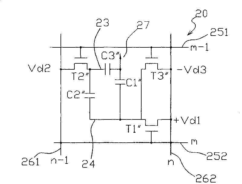
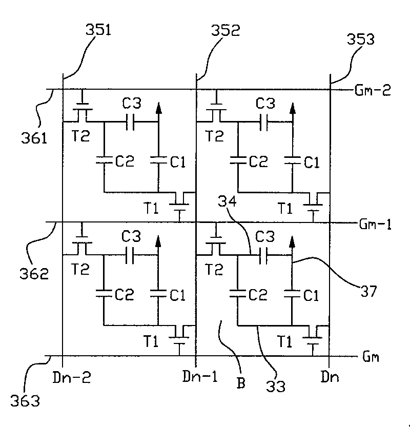
However, as we know, to redesign a driver, especially a source driver, it will consume considerable cost, in view of this, it is expected to target Figure 4 The pixel matrix 400 proposes an improved liquid crystal display panel and a driving method to solve this problem

Method used


Image

  • Liquid crystal display panel and driving method thereof
  • Liquid crystal display panel and driving method thereof
  • Liquid crystal display panel and driving method thereof

Examples


Embodiment Construction

[0084] Figure 5 It is a schematic diagram of an equivalent circuit of a liquid crystal display panel according to the first embodiment of the present invention, wherein the liquid crystal display panel 501 includes an n×m pixel matrix 500, and its overall structure is the same as that of the pixel matrix 400 in Figure 4, with n pixel columns and There are m pixel rows, and the pixels in it are controlled by n+1 data lines and m+1 scanning lines, and the connection between each thin film transistor and capacitor in each pixel is the same as that in the fourth figure, so The details are not repeated here, and the same components are denoted by the same symbols. The source driver 502 has n signal source output pins (signal output pin) P 1 ~P n , providing n data source signals to n+1 data lines of the pixel matrix 500 . And in order to solve the problem that the total number of data signals of the source driver 502 cannot match the total number of data lines, the present inve...


PUM


Abstract

The present invention relates to a LCD panel and the driving method thereof, comprising a pixel matrix. The pixel matrix comprises a plurality of pixels formed by the mutual intersection of a plurality of data lines and scan lines, wherein, each pixel comprises a first thin film transistor, a second thin film transistor, a control electrode and a pixel electrode. The first thin film transistor has a first electrode connected to one data line, a second electrode connected to the pixel electrode, and a grid electrode connected to one scan line. The second thin film transistor has a first electrode connected to the other adjacent data line, a second electrode connected to the control electrode, and a grid electrode connected to the other adjacent scan line, wherein, either of two outmost data lines of the pixel matrix is called a boundary data line; the boundary data line is connected with the other nonadjacent data line, and an auxiliary line is arranged between the boundary data line and the adjacent pixel electrode. Besides having the characteristic of wide visual angle, the LCD panel can collocate with the prior source electrode driver to operate pixels, and can simultaneously improve the problems of signal delay and parasitic capacitance asymmetry possibly produced in the transmission process of data signals.

Description

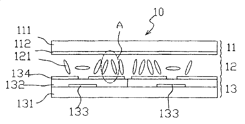
technical field [0001] The invention relates to a liquid crystal display panel and a driving method thereof, in particular to a liquid crystal display panel and a driving method thereof for improving the supply mode of data line signals and compensating related parasitic capacitance effects. Background technique [0002] With the wide application of liquid crystal display panels, users have higher and higher requirements on the quality of liquid crystal display panels, such as high brightness, high contrast, high resolution, high color saturation and fast time response. Especially as the area of ​​the panel increases, it has become an important application of the liquid crystal display panel to make a household flat display, such as a liquid crystal television, using the liquid crystal display panel. Generally, traditional liquid crystal display panels have narrow viewing angles, and normal images can only be viewed from the front of the liquid crystal display panel. If you ...

Claims


Application Information

Patent Timeline
Patent Type & Authority Patents(China)
IPC IPC(8): G02F1/133G02F1/136G09G3/36
Inventor 潘轩霖施博盛
Owner HANNSTAR DISPLAY CORPORATION
Learn More