Four-piece type optical lens group for imaging

An optical mirror and four-piece technology, applied in the field of lens groups, can solve problems such as manufacturing difficulties, lack of system freedom, and difficulty in shortening the overall length of the optical system, and achieve the effects of correcting aberrations, improving correcting astigmatism, and reducing length

Active Publication Date: 2011-02-16
LARGAN PRECISION
View PDF0 Cites 0 Cited by
  • Summary
  • Abstract
  • Description
  • Claims
  • Application Information

AI Technical Summary

Problems solved by technology

[0004] First, too many configurations of spherical mirrors make the degree of freedom of the system insufficient, making it difficult to shorten the overall length of the optical system;
[0005] Second, the glass lens bonding process is not easy, causing difficulties in manufacturing

Method used


Image

  • Four-piece type optical lens group for imaging
  • Four-piece type optical lens group for imaging
  • Four-piece type optical lens group for imaging

Examples


no. 1 example

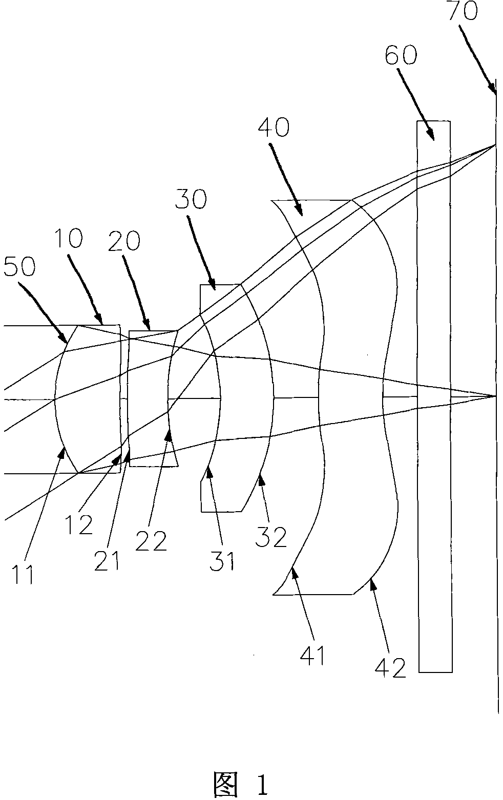
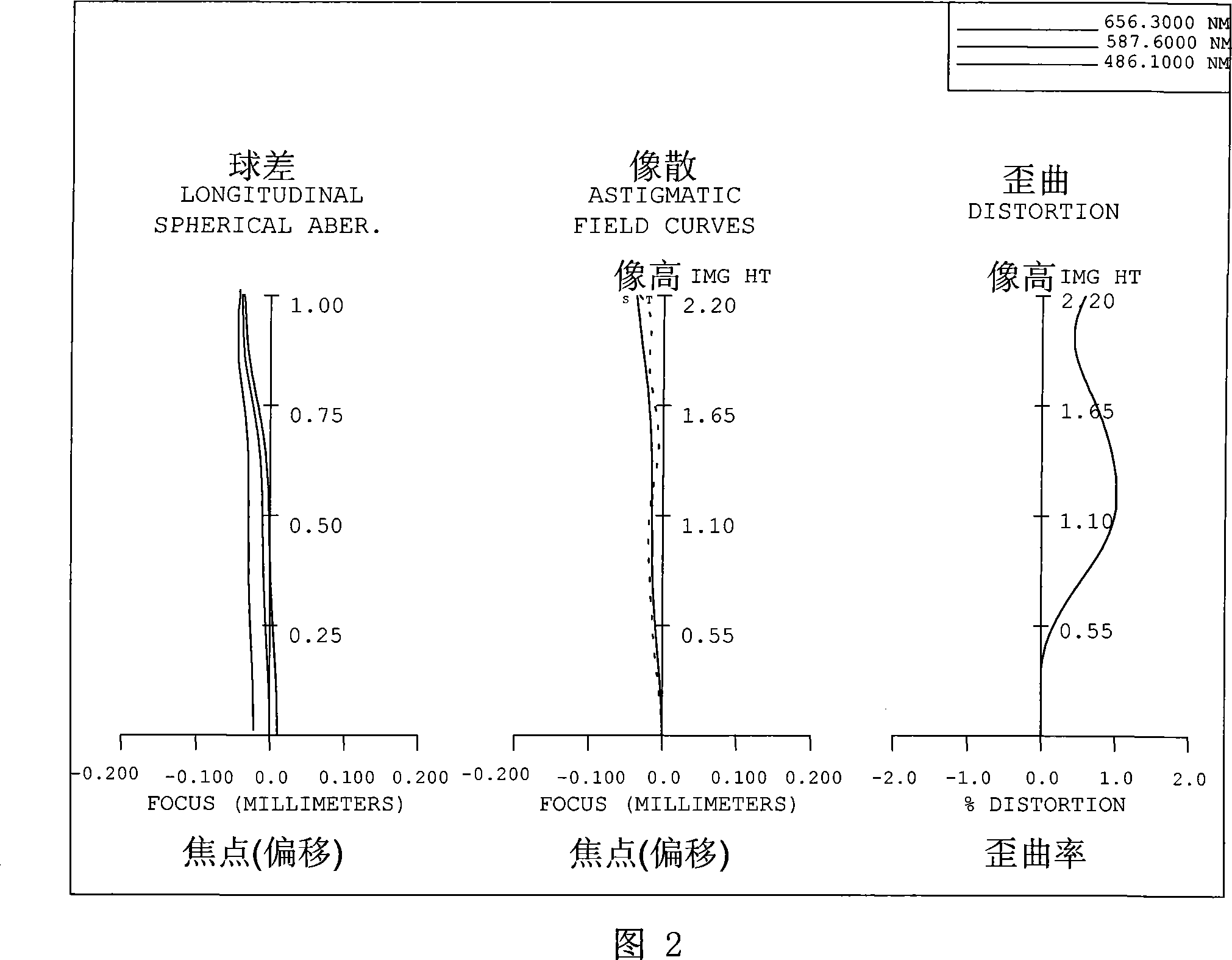
[0044] Please refer to the first embodiment of the present invention figure 1 , for the aberration curve of the first embodiment, please refer to figure 2 , the first embodiment includes from the object side to the image side:

[0045] A first lens 10 with positive refractive power is made of plastic, the first lens 10 has a front surface 11 and a rear surface 12, and the front surface 11 of the first lens 10 is a convex surface, and the rear surface 12 of the first lens 10 is Concave surface, and the front surface 11 and the rear surface 12 of the first lens 10 are all set as aspherical surfaces;

[0046] A second lens 20 with negative refractive power is made of plastic. The second lens 20 has a front surface 21 and a rear surface 22. The front surface 21 of the second lens 20 is convex, and the rear surface 22 of the second lens 20 is concave. , and both the front surface 21 and the rear surface 22 of the second lens 20 are aspherical;

[0047] A crescent-shaped third l...

no. 2 example

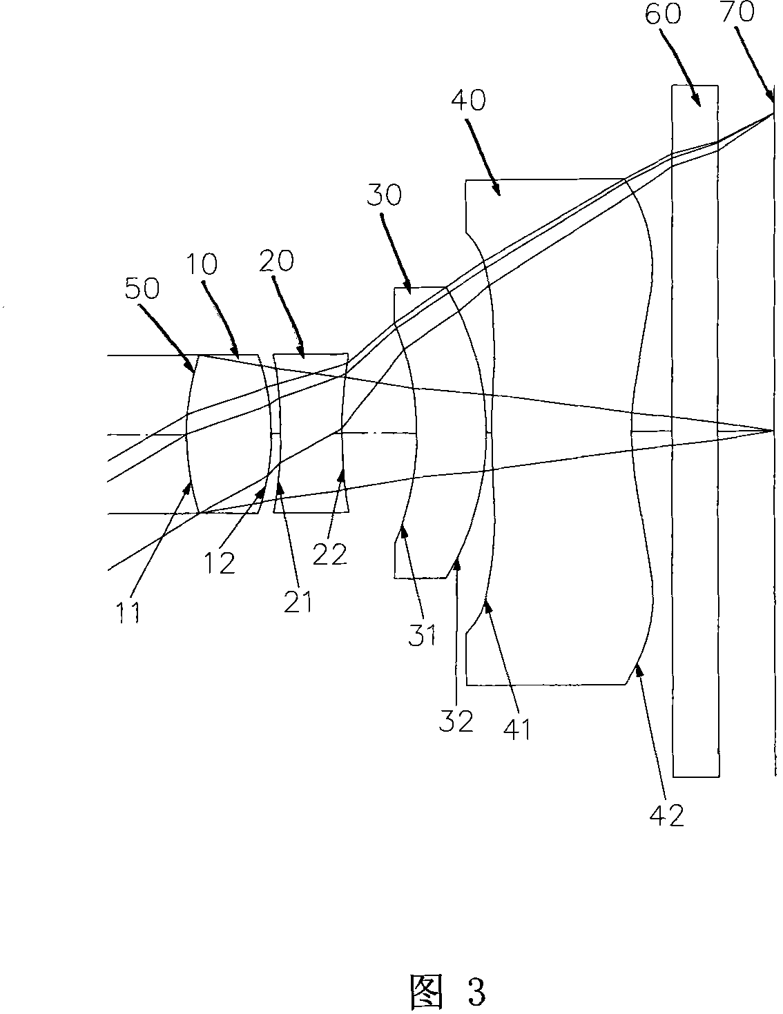
[0086] Please refer to the second embodiment of the present invention image 3 , for the aberration curve of the second embodiment, please refer to Figure 4 , the second embodiment includes from the object side to the image side:

[0087] A first lens 10 with positive refractive power is made of plastic, the first lens 10 has a front surface 11 and a rear surface 12, and the front surface 11 of the first lens 10 is a convex surface, and the rear surface 12 of the first lens 10 is convex surface, and the front surface 11 and the rear surface 12 of the first lens 10 are all set as aspherical surfaces;

[0088] A second lens 20 with negative refractive power is made of plastic, the second lens 20 has a front surface 21 and a rear surface 22, and the front surface 21 of the second lens 20 is concave, and the rear surface 22 of the second lens 20 is Concave surface, and the front surface 21 and the rear surface 22 of the second lens 20 are all set as aspherical surfaces;

[008...

no. 3 example

[0119] Please refer to the third embodiment of the present invention Figure 5 , for the aberration curve of the second embodiment, please refer to Figure 6 , the third embodiment includes from the object side to the image side:

[0120]A first lens 10 with positive refractive power is made of glass, the first lens 10 has a front surface 11 and a rear surface 12, and the front surface 11 of the first lens 10 is a convex surface, and the rear surface 12 of the first lens 10 is convex surface, and the front surface 11 and the rear surface 12 of the first lens 10 are all set as aspherical surfaces;

[0121] A second lens 20 with negative refractive power is made of plastic, the second lens 20 has a front surface 21 and a rear surface 22, and the front surface 21 of the second lens 20 is concave, and the rear surface 22 of the second lens 20 is Concave surface, and the front surface 21 and the rear surface 22 of the second lens 20 are all set as aspherical surfaces;

[0122] O...


PUM


Abstract

The invention discloses an optical four-lens unit for imaging, which comprises a first lens with positive refraction power, a second lens with negative refraction power, a crescent-shaped third lens with negative refraction power, and a fourth lens with negative fraction power which are disposed sequentially from the object side to the image side. The front surface of the first lens is a convex surface, the rear surface of the second lens is a concave face, at least one aspherical face is arranged on the second lens, the rear surface of the third lens is a convex surface, the front surface ofthe fourth lens is a convex surface, and the rear surface of the further lens is an aspherical face. With the lens structure, arrangement mode and lens configuration, the volume of the lens unit can be effectively reduced, and higher resolving power can be obtained.

Description

technical field [0001] The invention relates to a lens group, in particular to a miniaturized four-chip imaging optical mirror group applied to a camera phone. Background technique [0002] In recent years, with the rise of mobile phone cameras, the demand for miniaturized photographic lenses has been increasing, and the photosensitive components of general photographic lenses are nothing more than charge coupled devices (Charge Coupled Device, CCD) or complementary metal oxide semiconductors (Complementary Metal- OxideSemiconductor, CMOS) two, due to the advancement of semiconductor process technology, the pixel area of ​​the photosensitive component is reduced, and the miniaturized photographic lens is gradually developing into the high-pixel field. Therefore, the requirements for imaging quality are also increasing. [0003] The existing high-resolution mobile phone lenses mostly use a front aperture and a four-piece lens group. Among them, the first lens and the second l...

Claims


Application Information

Patent Timeline
Patent Type & Authority Patents(China)
IPC IPC(8): G02B13/00G02B9/34
Inventor 陈俊杉汤相岐
Owner LARGAN PRECISION
Why Eureka
Try Eureka