Light-splitting stereoscopic vision device for detecting interior of high-temperature narrow cavity

A stereoscopic vision and spectroscopic technology, which is applied to TVs, color TVs, components of color TVs, etc., can solve the problems of difficult to meet the measurement environment parameters, unable to adapt to detection, limited viewing angle, etc. The effect of wide viewing angle

Pending Publication Date: 2020-08-25
UNIV OF SCI & TECH OF CHINA
View PDF0 Cites 0 Cited by
  • Summary
  • Abstract
  • Description
  • Claims
  • Application Information

AI Technical Summary

Problems solved by technology

Its volume is too large to adapt to the internal detection of the above-mentioned ultra-high temperature narrow cavity
[0004] The conventional single-camera binocular detection method often uses a binocular observation device with split screens to use part of the camera's target surface for imaging, and its viewing angle is relatively limited, which is difficult to meet the constraints of the measurement environment parameters

Method used


Image

  • Light-splitting stereoscopic vision device for detecting interior of high-temperature narrow cavity
  • Light-splitting stereoscopic vision device for detecting interior of high-temperature narrow cavity
  • Light-splitting stereoscopic vision device for detecting interior of high-temperature narrow cavity

Examples


Embodiment 1

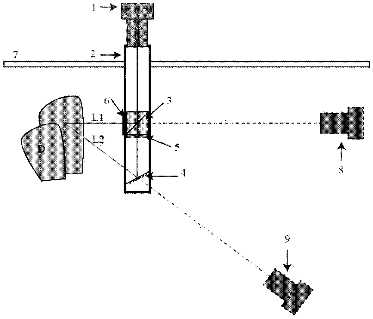
[0037] Embed the high temperature optical mirror barrel in the system into the interface 7 of the high temperature container. There is D object to be measured inside the high temperature container. The color spectroscopic imaging part 1 is set outside the high-temperature narrow cavity; the high-temperature optical lens barrel 2 is set inside the high-temperature narrow cavity. A color chip 5 and a blue spectrum color filter 6, wherein the light of the real image of the object is reflected by the above-mentioned reflector 4, then filtered by the above-mentioned red spectrum color filter 5, passes through the above-mentioned semi-transparent mirror 3, and then enters the above-mentioned color camera 1 Imaging: the light reflected by the object is filtered by the above-mentioned blue spectrum filter 6, and then reflected by the above-mentioned reflector 3, and enters the above-mentioned color camera 1 for imaging. Through the first and second pictures of different viewing angle...

Embodiment 2

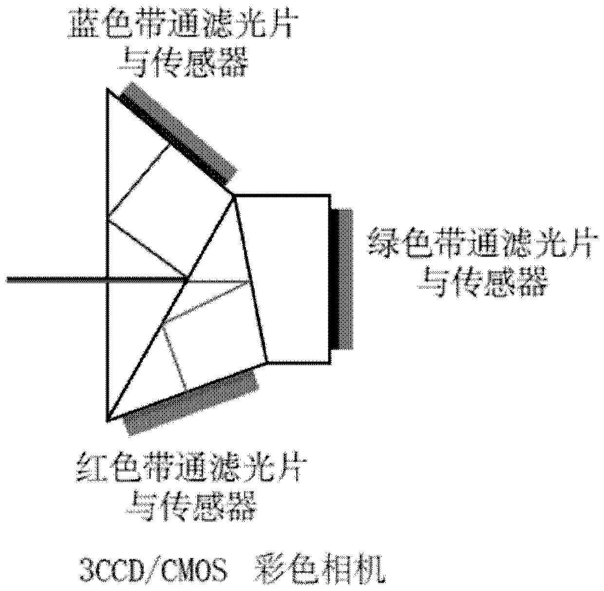
[0040] The difference between this embodiment and embodiment 1 is that a group of color cameras, half-transparent mirrors, red spectral filters and blue spectral filters are added above the interface of the high-temperature container to form a dual-camera spectroscopic stereoscopic device , whose structure is shown in the Figure 4 shown.

[0041] The above-mentioned spectroscopic stereoscopic vision device can be used for detection of objects inside the aero-engine, etc., and it is applied to the three-dimensional side view schematic diagram of the aero-engine as shown in Figure 5 shown.


PUM


Abstract

A light-splitting stereoscopic vision device is used for detecting an object in a high-temperature narrow cavity and comprises a color light-splitting imaging module arranged outside the high-temperature narrow cavity and used for imaging an object; a high-temperature optical lens cone arranged in the high-temperature narrow cavity, wherein a semi-transparent reflector, a reflector, a red spectrum color filter and a blue spectrum color filter are arranged in the high-temperature optical lens cone, and light of an object real image is reflected by the reflector, filtered by the red spectrum color filter, penetrates through the semi-transparent reflector and then enters the color spectral imaging module to be imaged; light reflected by an object is filtered by the blue spectrum color filter, then is reflected by the reflector, and enters the color light splitting imaging module to be imaged. By arranging the double reflectors and the color light splitting device in the high-temperatureoptical tube lens, a light path with small size and strong high-temperature bearing capacity is formed, the requirement for detection inside a high-temperature narrow cavity is met, and light paths with different visual angles can be output to be provided for a camera outside the high-temperature cavity.

Description

technical field [0001] The invention relates to the field of computer vision and monitoring, in particular to a spectroscopic stereoscopic vision device for detecting inside a high-temperature narrow cavity. Background technique [0002] The on-line detection of displacement and strain of mechanical components in high-temperature environments is widely required but difficult, especially for closed and narrow environments such as aero turbine engines, where the space left for detection equipment is very small, and the ambient temperature may be between 500 and 1200 degrees Celsius. The working conditions were very bad. The strain field measurement of its blades under high-speed rotating conditions has always been a key problem that the industry expects to solve. [0003] In conventional stereo digital image correlation or other computer binocular stereo vision applications, two similar cameras need to be used to observe the measured object with a certain stereo perspective. ...

Claims


Application Information

Patent Timeline
Patent Type & Authority Applications(China)
IPC IPC(8): H04N5/225
CPCH04N23/555H04N23/54H04N23/55
Inventor 张青川薛伟伟
Owner UNIV OF SCI & TECH OF CHINA
Why Eureka
Try Eureka