
Computer super module and super modular computer

A computer and modular technology, applied in mechanical equipment, coupling devices, electrical components, etc., can solve the problems of high connection and assembly technical requirements, poor scalability, poor module interchangeability, etc., to facilitate cyclic expansion and upgrade, and convenient assembly and disassembly , good protective effect

Inactive Publication Date: 2008-06-25
杨伍民
View PDF0 Cites 11 Cited by
  • Summary
  • Abstract
  • Description
  • Claims
  • Application Information

AI Technical Summary

Problems solved by technology

Prior art computer modules, and the deficiencies of the computer complete machine assembled by modules mainly lie in four aspects: 1. Notebook computers are limited in volume and structure, high in price, poor in interchangeability of modules, poor in expansibility, and limited in use. Restrictions; 2. Desktop computers are bulky and heavy, and the wiring between the modules inside the case is messy, which can be seen by opening any desktop case; 3. The overall hardware structure and volume of the desktop computer, in the selected case After being connected to the main board of the motherboard module, it cannot be changed, and the system configuration is inflexible; 4. It is difficult for ordinary users without professional knowledge to use the commodity module to configure and upgrade the computer system by themselves; due to the increasingly widespread use of computers, different users have different Time often has different requirements for computer functions or configurations, which may require frequent assembly, disassembly, and reassembly of computers and their modules, and it is best to be able to be flexibly assembled and disassembled by users at any time, which is more economical and convenient; but , the current computer products have various types of modules and interfaces, high requirements for connection and assembly technology, and it is difficult for users to disassemble, install and upgrade as they like.

Method used


Image

  • Computer super module and super modular computer
  • Computer super module and super modular computer
  • Computer super module and super modular computer

Examples


Embodiment 1

[0059] Embodiment one: if Figure 10 As shown, the extended computer supermodule 90 is directly installed on the top of the chassis 2 of the host system 1, and the chassis 2 is designed as a vertical chassis, and a series-connected extended computer supermodule is adopted;

Embodiment 2

[0060] Embodiment two: if Figure 11 As shown, the extended computer supermodule 90 is directly installed on the top of the chassis 2 of the host system 1, the chassis 2 is designed as a horizontal wide-width chassis, and at least two extended computer supermodules 90 are extended side by side on the top of the chassis;

Embodiment 3

[0061] Embodiment 3: As shown in FIG. 12, an extended computer super module 90 is installed inside the chassis 2 in an embedded manner, and above the extended computer super module 90, there is a accommodating space 21;


PUM


Abstract

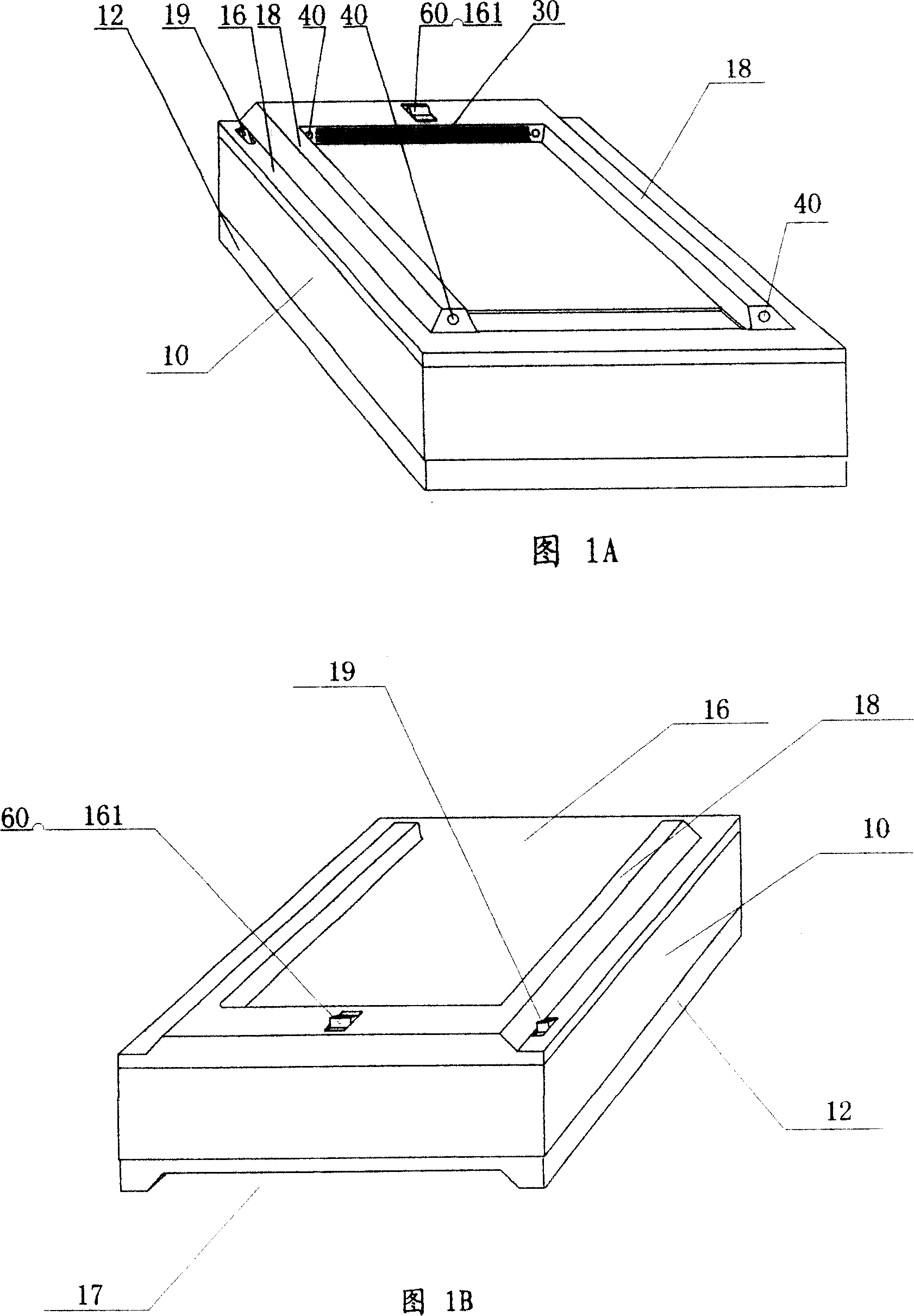
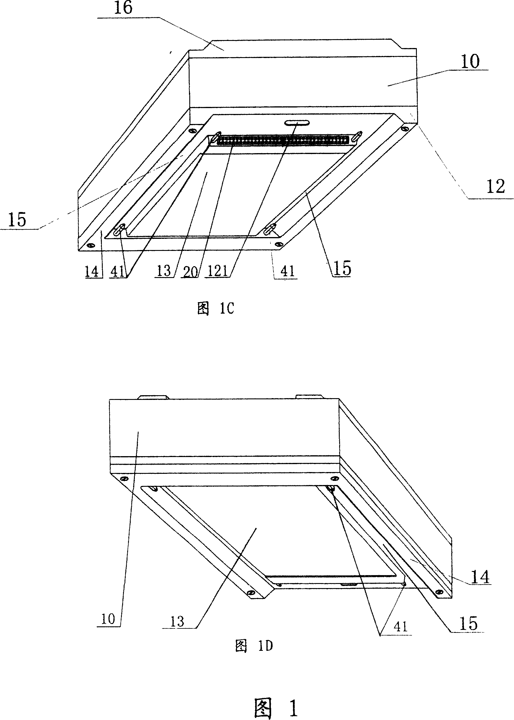
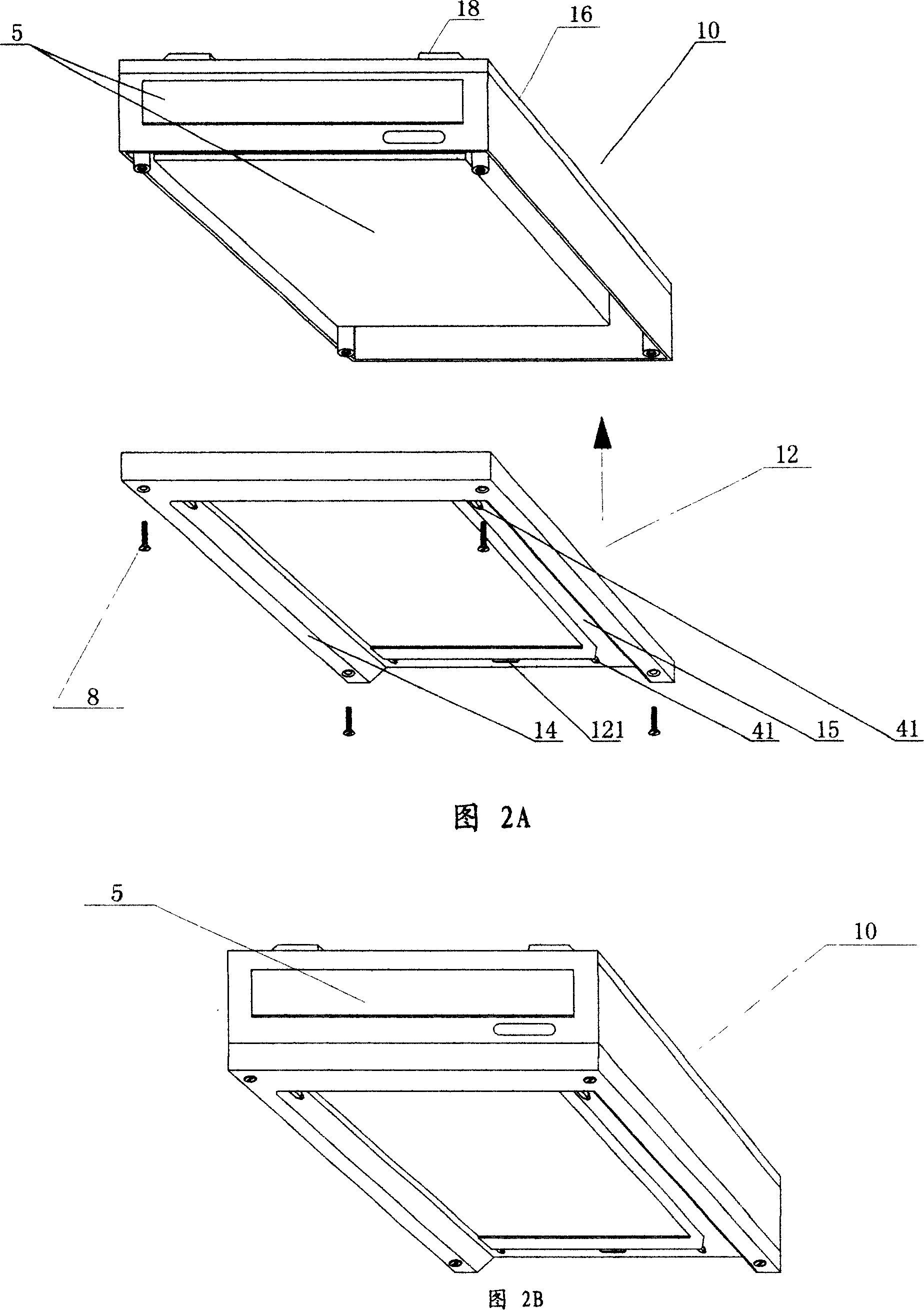
The invention relates to a computer supermodule and a super modularization computer. A hardware interface(11) is arranged in the shell (10)of the computer supermodule, and a porous socket (20)is arranged at the front-end of the lower surface of the shell, which is connected electrically to the hardware interface(11) from inside by means of cable; Two guide slots (15)are arranged on the bottom cover(12) and at the two sides of the porous socket (20), which adapt two guide rails(18) positioned on and near the left and right sides of the top cover (16) of the shell (10), and a multipin plug(30) is positioned on front-end of the top cover (16),which adapts to the porous socket(20) and is connected electrically to the porous socket (20) inside the shell(10).The invention is capable of realizing free fit and guide positioning splice between supermodules and between the supermodules and the super modularization computer, which makes the system configuration of computer flexible and convenient, the extensibility strong and the operation of upgrade simple. Common user can operate freely without too much professional knowledge.

Description

technical field [0001] The invention relates to a general digital computer, in particular to a computer super module and a super modular computer. Background technique [0002] As we all know, digital computers, including PCs or personal computers, are product systems composed of modules. Taking a personal computer PC as an example, it is generally composed of modules with quite independent functions, certain interchangeability, compatibility, expansion performance and external interfaces, such as various boards, cards, CPUs, radiators and fans, hard disks, optical drives, etc. etc., as the constituent unit of the computer. In the prior art, the process of assembling a complete computer from dispersed modules is usually completed by manual insertion, screw connection, fastening and the like. Prior art computer modules, and the deficiencies of the computer complete machine assembled by modules mainly lie in four aspects: 1. Notebook computers are limited in volume and struc...

Claims


Application Information

Patent Timeline
IPC IPC(8): G06F1/18H01R13/631H01R13/24F16H37/00H05K5/00
Inventor 杨伍民
Owner 杨伍民
Learn More