Magnetic force assistant slide locating mechanism

A positioning mechanism and magnetic technology, applied in the direction of telephone structure, electrical equipment structural parts, casing/cabinet/drawer parts, etc. Small overall size, impact reduction effect

Inactive Publication Date: 2008-06-25
BENQ CORP
View PDF0 Cites 21 Cited by
  • Summary
  • Abstract
  • Description
  • Claims
  • Application Information

AI Technical Summary

Problems solved by technology

[0004] Secondly, for those who utilize surface tension, it is usually to use the surface tension difference between the liquid and the relative fixed member and the relative movable member to pull the movement of the relative movable member. Since the surface tension is usually very small, only Unpowered sliding positioning mechanism suitable for extremely small (such as micron and nanoscale dimensions)

Method used


Image

  • Magnetic force assistant slide locating mechanism
  • Magnetic force assistant slide locating mechanism
  • Magnetic force assistant slide locating mechanism

Examples


Embodiment Construction

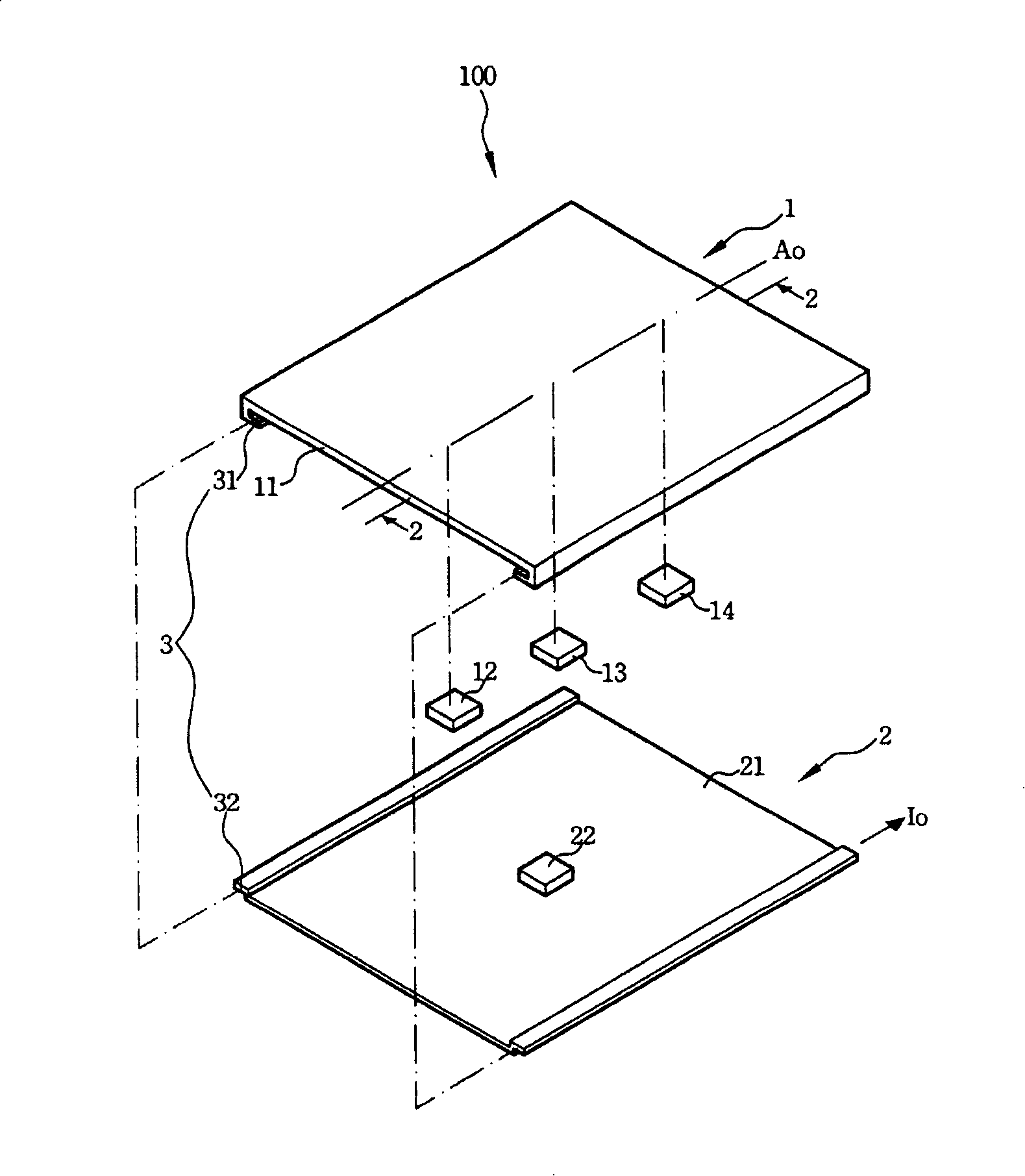
[0078] see image 3 , which shows an exploded perspective view of the first embodiment of the present invention. As shown in the figure, a magnetic-assisted sliding positioning mechanism 200 includes a first platform 4 , a second platform 5 and a sliding guide assembly 6 .

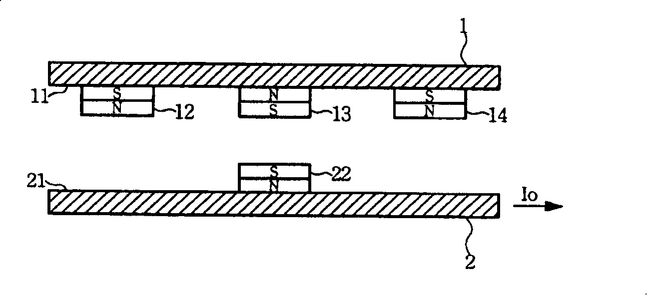
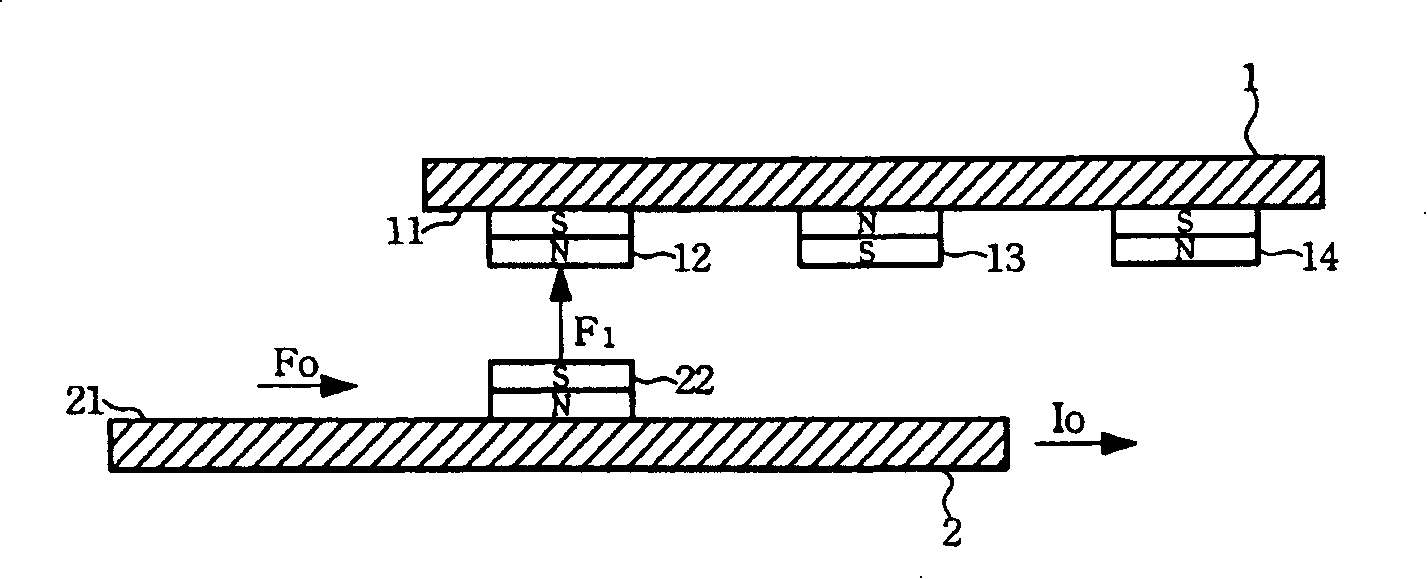
[0079] The first platform 4 has a first working surface 41 on which a double-sided rack 42 and two first magnets 43 and 44 are disposed. Wherein, the first magnets 43 and 44 are disposed at both ends of the double-sided rack 42, and they all have a first magnetic pole (N pole in this embodiment, hereinafter replaced by N pole) and a second magnetic pole (in the In this embodiment, it is the S pole, which will be replaced by S pole below), and the first magnetic poles of the first magnets 43 and 44 are arranged facing each other, and the two sides of the double-sided rack 42 respectively have a rack portion 421 and 422 .

[0080] The second platform 5 has a second working surface 51 , and the second worki...


PUM


Abstract

The invention discloses a sliding locating mechanism assisted by magnets, and the mechanism comprises a first platform and a second platform. The first platform is combined with a double-sided rack and two first magnets. The two first magnets are arranged on the two ends of the double-sided rack and provided with first magnetic poles and second magnetic poles, and the first magnetic poles of the two first magnets are arranged oppositely to each other. The second platform is combined with two magnetic gear wheels which are articulated with the two sides of the double-sided rack, and the two magnetic gear wheels are both provided with the first magnetic poles and the second magnetic poles. When a relative sliding motion is acted between the first platform and the second platform, the two magnetic gear wheels are driven to rotate by meshing with the double-sided rack in a rotating way; when the two magnetic gear wheels are rotated to the middle of the double-sided rack, the first magnetic poles of the two magnetic gear wheels repel each other; when the two magnetic gear wheels are rotated to the two ends of the double-sided rack, the second magnetic poles of the two magnetic gear wheels and the first magnetic poles of the first magnets attract each other.

Description

technical field [0001] The invention relates to a sliding positioning mechanism, in particular to a sliding positioning mechanism assisted by magnetic force. Background technique [0002] Looking at the existing non-power-assisted sliding positioning mechanisms, most of them have a relatively movable part and a relatively immovable part, and use the contact force and over-distance force existing in nature such as gravitation, surface tension and magnetic force to guide the relatively movable part. The movement of the part, and through the guidance of the sliding guide assembly, the relative movable part can be slid and positioned to the selected position fully or semi-automatically. [0003] Among them, the gravitational force mostly uses the gravity of the counterweight to guide the movement of the relative movable part. Because driving the movement of the relative movable part usually has to overcome a considerable mechanical friction force, it must usually be combined wit...

Claims


Application Information

Patent Timeline
Patent Type & Authority Applications(China)
IPC IPC(8): H05K5/03H05K7/00H04M1/02
Inventor 王京禄
Owner BENQ CORP
Why Eureka
Try Eureka