
Fuel vapor systems for internal combustion engines

A technology of fuel vapor, internal combustion engine, applied in the field of systems, capable of solving problems for which solutions have not yet been found

Inactive Publication Date: 2008-06-25
FINE TUNING
View PDF0 Cites 10 Cited by
  • Summary
  • Abstract
  • Description
  • Claims
  • Application Information

AI Technical Summary

Problems solved by technology

Pre-evaporation of fuel has been proposed for decades as a way to improve fuel efficiency and reduce emissions from internal combustion engines, but no acceptable solution has yet been found

Method used


Image

  • Fuel vapor systems for internal combustion engines
  • Fuel vapor systems for internal combustion engines
  • Fuel vapor systems for internal combustion engines

Examples


Embodiment Construction

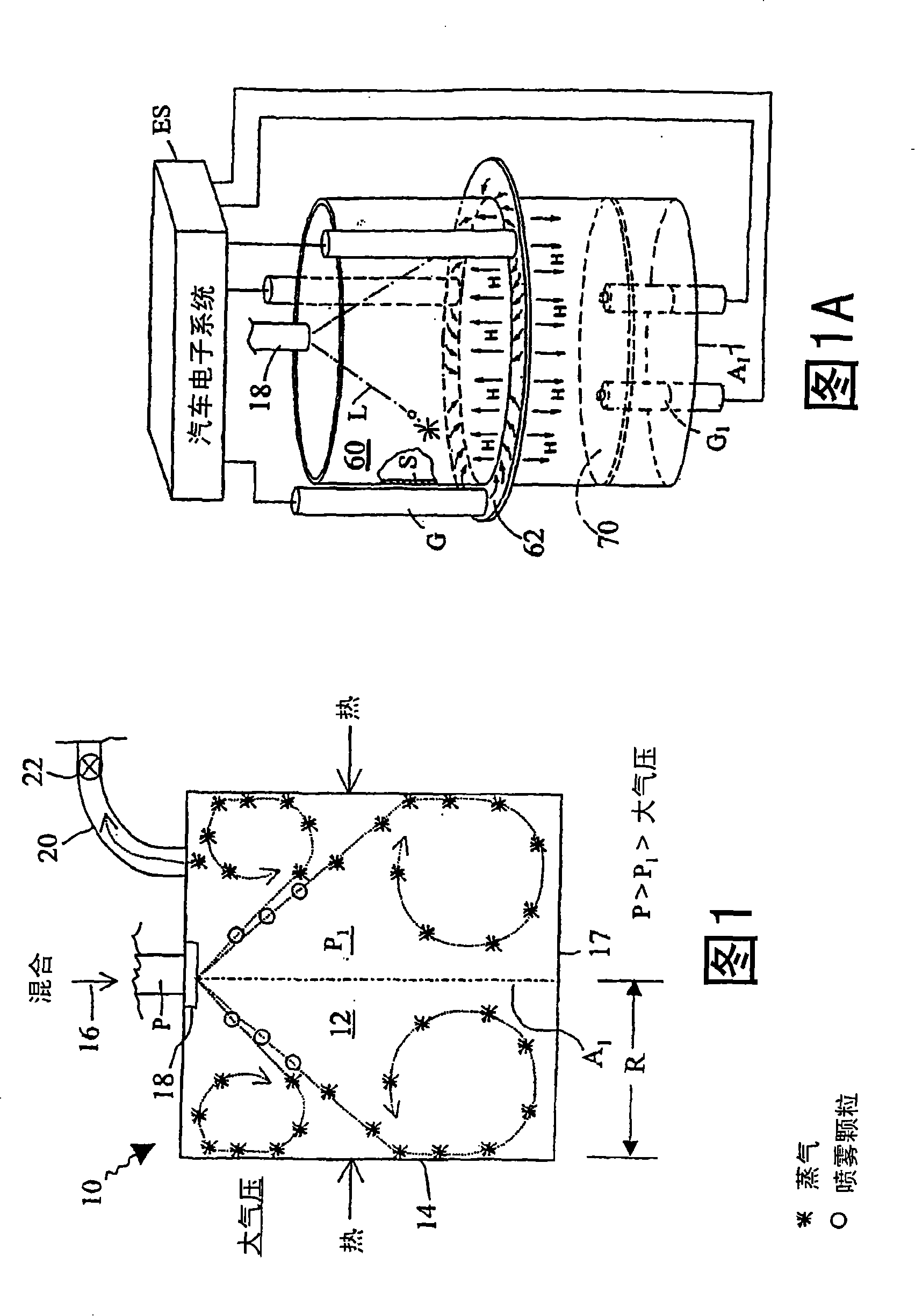
[0119] Referring to FIG. 1 , a vaporization chamber 10 vaporizes liquid fuel in a chamber 12 . The evaporation operation is the process by which liquid fuel particles are converted into a gaseous state in which very fine, dispersed residual liquid particles may also be suspended. For example, the lighter components of liquid fuel particles will be completely converted to gas, while the heavier components will be partially converted to gas, and the remaining extremely fine particles will have a large total area, which will facilitate rapid heating and combustion in the engine.

[0120] A closed pressure chamber, comprising a cylindrical wall 14 and end walls 15 , 17 , defines a volume 12 . As indicated by the arrows, the cylindrical wall 14 is heated by an external heat source. Liquid fuel 16 arrives at vaporization chamber 10 from a pressure source and is pulsed into volume 12 by injector 18 . Injector 18 injects liquid fuel from an orifice or set of orifices into volume 12...


PUM


Abstract

Fuel is vaporized under substantial super-atmospheric pressure. Surfaces are heated by the engine's electrical system. Vapor heated by a wall bounding a vaporization space turbulently mixes with incoming liquid spray, helping to produce new vapor. Useful for cold start, liquid spray reaching a rapidly heated impact plate is vaporized. Multiple heat-transfer surfaces are exposed to the same vapor volume, one, a surface of revolution surrounding the spray, another, a transverse surface across the spray. The spray is in pulses. Glow plugs are arranged perpendicular to heat-distributing members. A volume-surrounding wall receives heat from an annular medium. A fuel vaporizer dedicated to a single combustion region has a cup-shaped vaporization chamber heated by a central heater in opposition to liquid spray. In such a system also having a vapor injection valve synchronized with engine timing, the internal between operations of the valves is controlled to enable heat-transfer to vaporize the fuel and build up pressure.

Description

technical field [0001] The present invention relates to systems that convert liquid fuels into fuel vapors to improve combustion in internal combustion engines. Background technique [0002] The way fuel is supplied to an engine can significantly affect fuel efficiency and exhaust emissions. In a piston engine with a carburetor, liquid gasoline is introduced centrally into the flow of combustion air, after which the air-fuel mixture is divided into portions and distributed to the individual cylinders of the engine. In a piston engine whose cylinders have fuel injectors, pressurized liquid fuel is forced through the nozzle of the injector to produce a spray of liquid fuel particles. The spray is injected into the combustion air at the intake port of the cylinder, or directly into the combustion zone. Incomplete combustion of fuel in these and other engines can adversely affect fuel economy and produce harmful emissions. Pre-evaporation of fuel has been proposed for decades...

Claims


Application Information

Patent Timeline
IPC IPC(8): F02G5/00
CPCY02T10/32Y02T10/125Y02T10/166Y02T10/12
Inventor 托马斯·D.·戴尔
Owner FINE TUNING
Learn More