water pump

A water pump and pool technology, applied in the direction of pumps, pump components, non-variable-capacity pumps, etc., can solve the problems of small conveying volume and high power consumption

Active Publication Date: 2011-12-14
OASE GMBH
View PDF4 Cites 0 Cited by
  • Summary
  • Abstract
  • Description
  • Claims
  • Application Information

AI Technical Summary

Problems solved by technology

Although this type of water pump generates a relatively high delivery pressure, it has a relatively small delivery volume
If large delivery volumes are to be achieved with such pumps, the necessary power consumption is very high

Method used


Image

  • water pump
  • water pump
  • water pump

Examples


Embodiment Construction

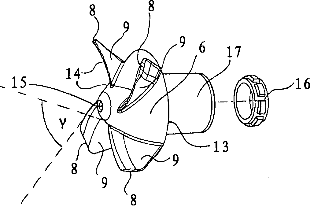
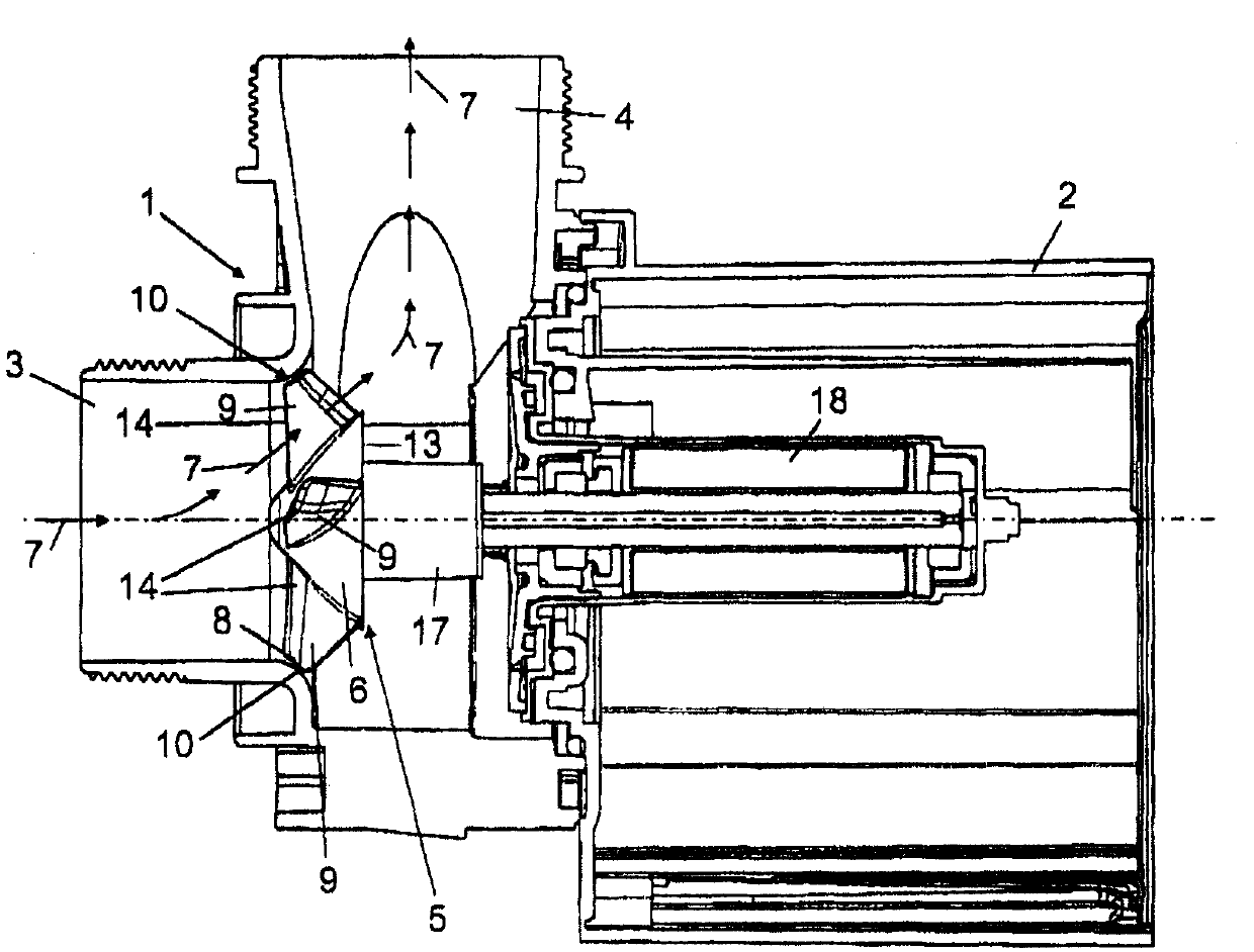
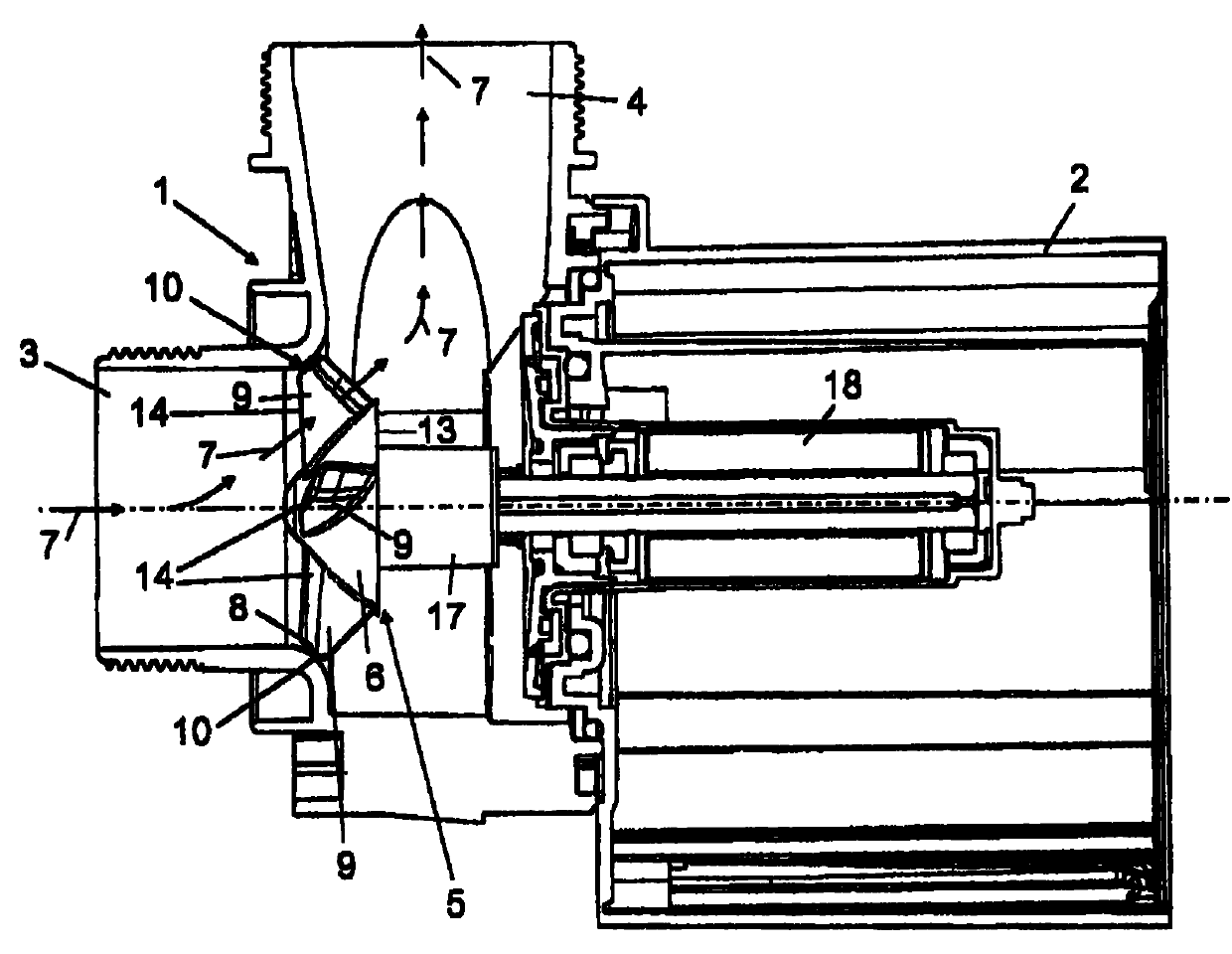
[0018] The water pump described has a pump housing 1 and a motor housing 2 connected thereto in a sealing manner, which together form the overall housing of the pump. The pump housing 1 has a water inlet 3 and a water outlet 4 which is preferably arranged centrally on the upper side of the pump housing. A pump impeller 5 designed as a diagonal flow impeller is arranged within the pump housing 1 between the water inlet 3 and the water outlet 4 . The pump impeller is figure 2 Represented in perspective.

[0019] According to the invention, the impeller 5 of the pump has a substantially conical cover plate 6 through which the water flow, indicated by the arrow 7 , is guided diagonally through the pump housing. As a result of the arrangement and shape of the water inlet 3 and the water outlet 4 , which are preferably substantially perpendicular to each other, the water flow 7 leaves the pump in a direction deflected by approximately 90° relative to the water flow inlet directio...


PUM


Abstract

The water pump, for garden ponds and aquaria, has a pump housing (1) with a water inflow (3) and outflow (4) and a diagonal powered impeller (5) with a conical covering disk (6). The water inflow and outflow are at right angles to each other. The leading edges (8) of the impeller paddles (9) are aligned at a diagonal, parallel to the water flow, forming a sealing gap (10) with the inner contour of the pump housing. The impeller is of an injection molded plastics with at least one metal ring.

Description

technical field [0001] The present invention relates to a water pump especially for use in garden ponds and aquatic life areas. Background technique [0002] In practice, pumps are common in this field, which have motor-driven radial impellers so that the water to be pumped is deflected by a deflection angle of 90°. The pump thus justifies the requirements in a corresponding arrangement, so that a deflection of approximately 90° must generally be carried out. Although such water pumps generate a relatively high delivery pressure, they have a relatively small delivery volume. If large delivery volumes are to be achieved with such pumps, the necessary power consumption is very high. Contents of the invention [0003] It is therefore the object of the present invention to provide a water pump with improved efficiency with regard to the delivery volume. [0004] The invention provides a water pump used in garden ponds and aquatic organisms areas, comprising a pump casing wi...

Claims


Application Information

Patent Timeline
Patent Type & Authority Patents(China)
IPC IPC(8): F04D1/04F04D29/18
CPCF04D29/183F04D29/2216F04D29/2255
Inventor A·汉克D·布鲁内I·格达尼茨
Owner OASE GMBH
Why Eureka
Try Eureka