
Method for forming part drawing modeling with dent structure

A technology of concave structure and parts, which is applied in the field of parts forming, can solve the problems of increasing defective rate, wrinkling on the surface of parts, and stacking, so as to prevent wrinkling and stacking, avoid wrinkling and stacking, and improve forming quality effect

Inactive Publication Date: 2008-07-02
BYD CO LTD
View PDF0 Cites 9 Cited by
  • Summary
  • Abstract
  • Description
  • Claims
  • Application Information

AI Technical Summary

Problems solved by technology

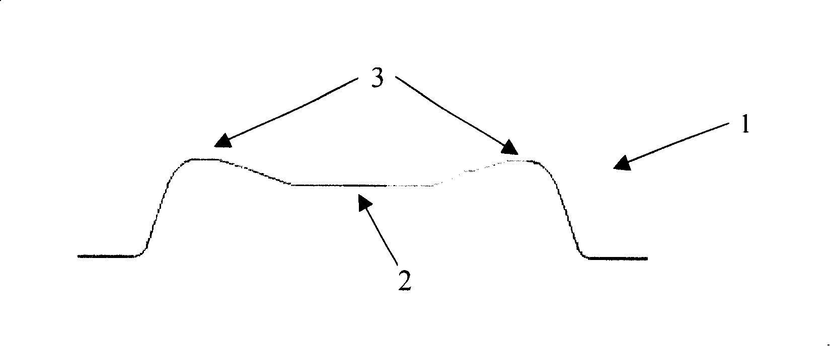
This drawing shape has a certain height difference in the entire shape, so the flow of the material cannot be well controlled during the drawing forming process, and aggregates are prone to appear in the transition part from the protruding part 3 to the concave part 2. Therefore, it will lead to wrinkling and stacking on the surface of the drawn part, which will seriously affect the forming quality of the final part and increase the defective rate

Method used


Image

  • Method for forming part drawing modeling with dent structure
  • Method for forming part drawing modeling with dent structure
  • Method for forming part drawing modeling with dent structure

Examples


Embodiment Construction

[0011] Next, with reference to the accompanying drawings, a detailed description will be given of the forming method of the drawing-formed part having a concave structure provided by the present invention.

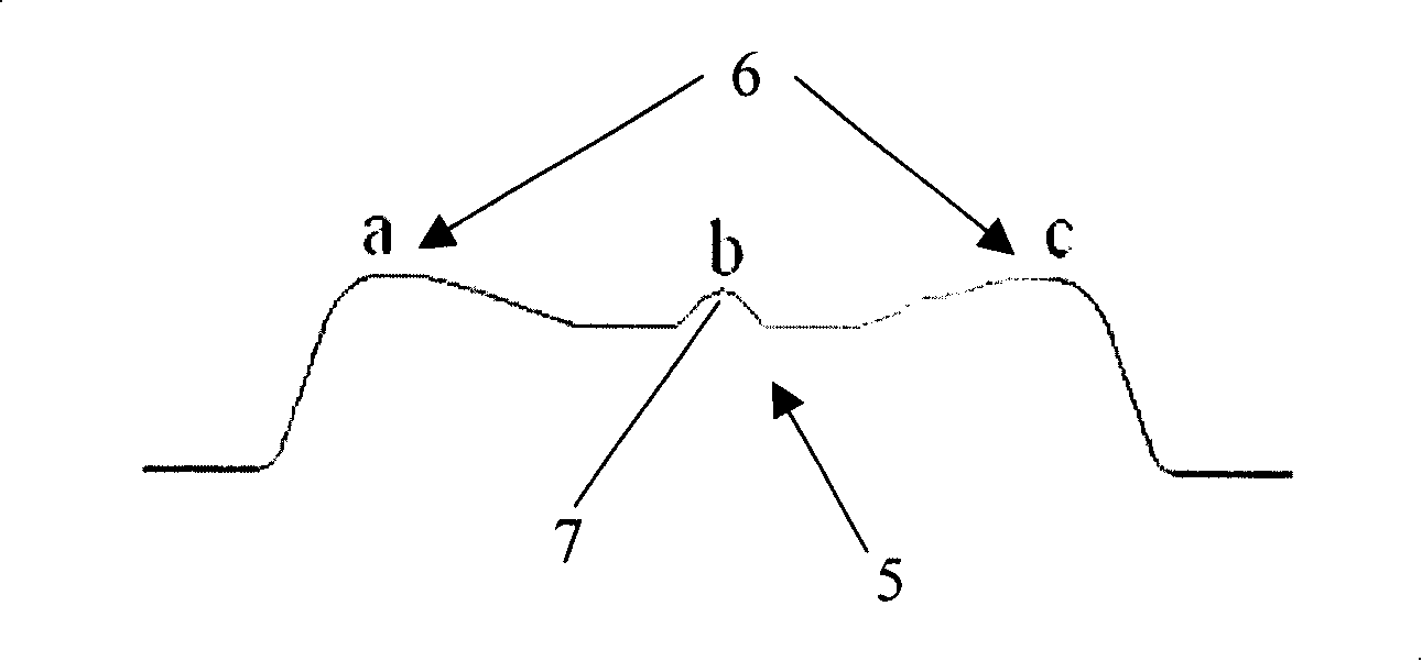
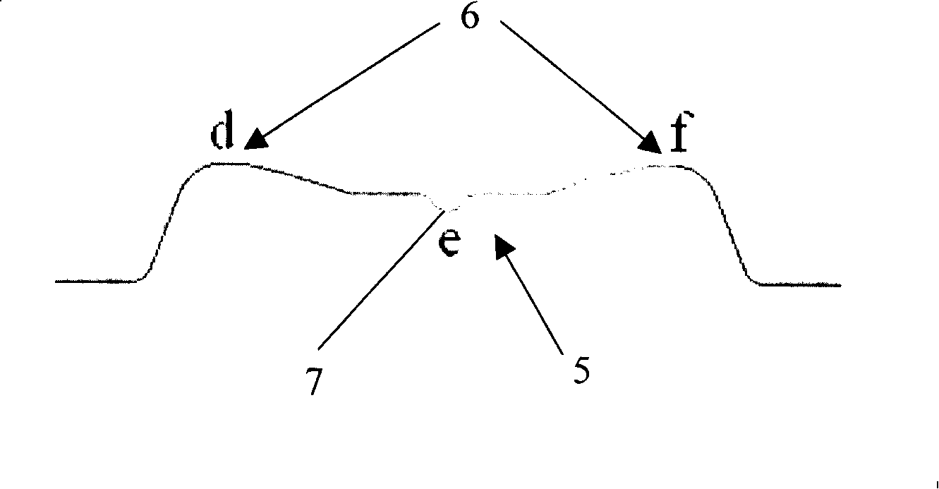
[0012] The method for forming a part with a concave structure by drawing according to the present invention includes: drawing and molding a sheet, wherein the drawn-shaped part includes a concave area 5 and a protruding area 6 located around the concave area 5, In addition, a suction rib 7 is formed in the recessed area 5 ; and then the drawn and shaped workpiece is punched to cut off the suction rib 7 .

[0013] Since the drawing shape of the part to which the present invention is applicable has a concave structure, such as figure 1 As shown, the center is low and the periphery is high, that is, there is a recessed portion 2 and a protruding portion 3 located around the recessed portion 2 . Therefore, when the sheet is drawn and shaped, it needs to be formed into a corre...


PUM


Abstract

The invention relates to a molding method for drawing and molding a part with depressed structure. The molding method comprises the steps that: a panel is draw and molded, the draw and molded part comprises a depressed area (5) and a protruding area (6) located around the depressed area (5), and a material gathering bar (7) is formed in the depressed area (5); then the draw and molded part is die cut so as to die cut the material gathering bar (7). During the drawing and molding process of the molding method for drawing and molding the part with the depressed structure, as the gathering bar is formed in the depressed area of the part, so the flow of the material can be well controlled during the drawing process; therefore, material accumulation is hard to occur in the transitional part from the protruding area to the depressed area, thus avoiding the wrinkle and laminated material on the surface of the part after drawing molding, enhancing the molding quality of the parts and reducing the defective rate.

Description

technical field [0001] The invention relates to a method for forming a part, more specifically, to a method for forming a part whose drawing shape has a concave structure, that is, the drawing shape is low in the middle and high in the periphery. Background technique [0002] In recent years, the stamping process has been widely used in the automobile manufacturing industry. Many covering parts and interior panels in the vehicle are formed by stamping with dies. Usually, complex parts generally need to go through multi-step processes such as drawing, trimming, flanging, and shaping to complete the shape. However, due to the limitation of shape and structure of some parts in actual production, after the drawing forming process, the surface of the part will appear in bad condition, which will lead to a decrease in the quality of the final product, or even waste. [0003] For example, figure 1 The drawing shape 1 of a part shown in , has a concave structure, low in the middle...

Claims


Application Information

Patent Timeline
Patent Type & Authority Applications(China)
IPC IPC(8): B21D22/26B21D22/30
Inventor 陈湘龙
Owner BYD CO LTD
Learn More