
Buffer in ultra-low power consumption integrated circuit

An integrated circuit, ultra-low power consumption technology, applied in the buffer field, can solve the problem of large punch-through current, and achieve the effect of avoiding conduction current

Active Publication Date: 2008-07-02
SHANGHAI HUAHONG INTEGRATED CIRCUIT
View PDF0 Cites 4 Cited by
  • Summary
  • Abstract
  • Description
  • Claims
  • Application Information

AI Technical Summary

Problems solved by technology

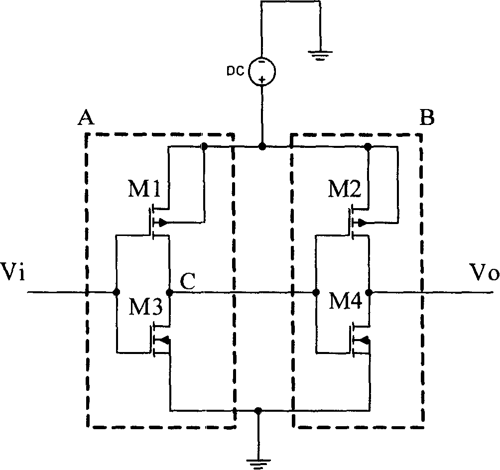
[0003] This kind of circuit structure is simple, but when the output voltage of the first-stage inverter jumps from "high" to "low" or from "low" to "high", it will make the PMOS transistor M2 and the NMOS transistor M4 be at the same time. In the sub-threshold state, the two tubes are turned on at the same time, and a large pass-through current is generated at this time, which should be avoided as much as possible for low-power integrated circuit design

Method used


Image

  • Buffer in ultra-low power consumption integrated circuit
  • Buffer in ultra-low power consumption integrated circuit

Examples


Embodiment Construction

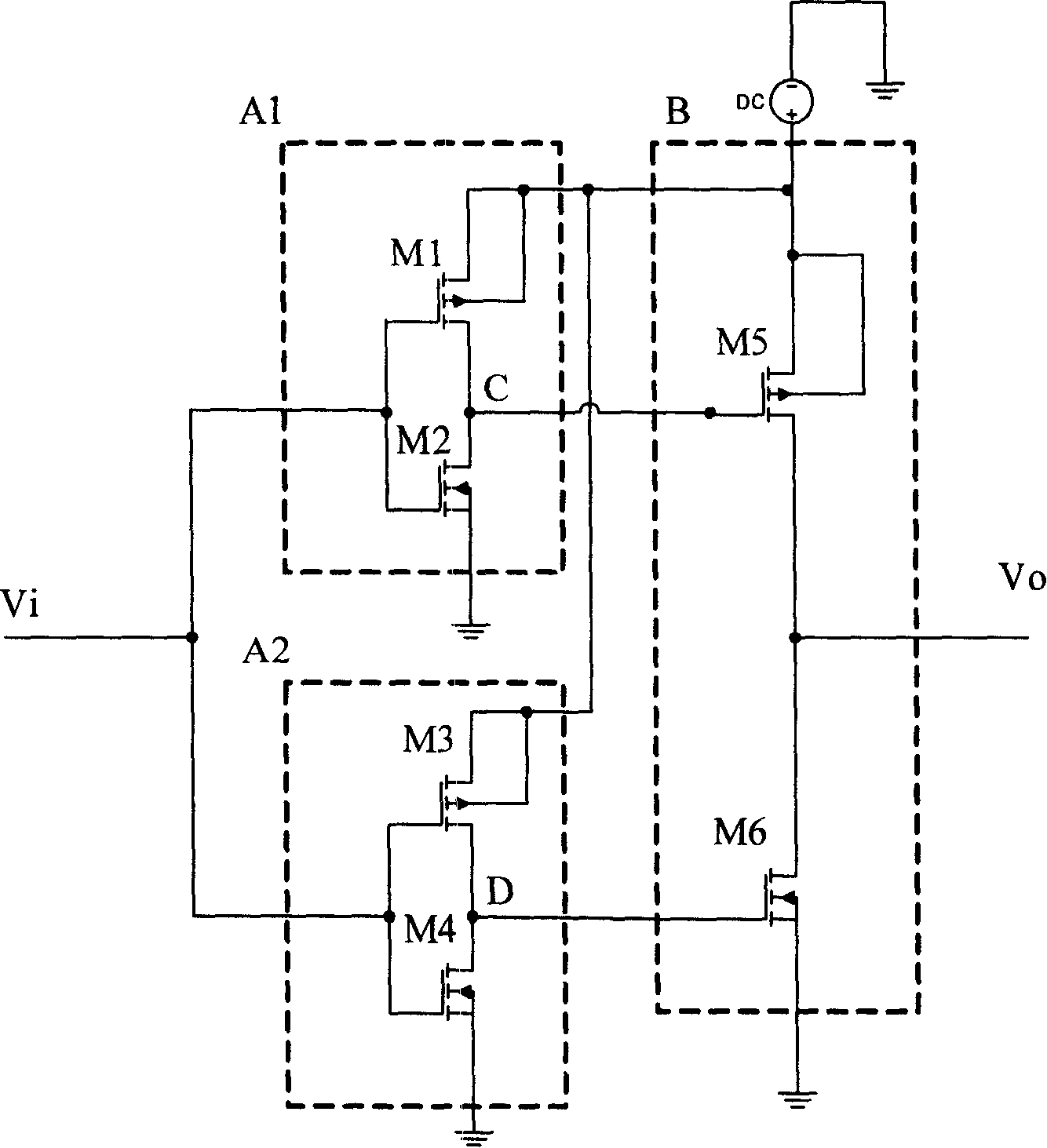
[0018] Attached below figure 2 The invention is further described in figure 2 , including two first-stage inverters A1 and A2, wherein the first-stage inverter A1 includes a series-connected PMOS transistor M1 and an NMOS transistor M2, and the gate of the PMOS transistor M1 is connected to the gate of the NMOS transistor M2. And connected to the voltage input terminal Vi, the gate of the PMOS tube M1 and the gate of the NMOS tube M2 are connected to the point C and serve as the output end of the first-stage inverter A1, the source of the PMOS tube M1 is connected to the power supply voltage, The source of the NMOS transistor M2 is grounded. The first-stage inverter A2 includes a PMOS transistor M3 and an NMOS transistor M4 connected in series. The gate of the PMOS transistor M3 is connected to the gate of the NMOS transistor M4 and is connected to the voltage input end Vi, and the gate of the PMOS transistor M3 is connected to the NMOS transistor. The gates of M4 meet at ...


PUM


Abstract

The invention discloses a buffer in an integrated circuit with ultra low power consumption. The invention applies voltage generated by two first level inverters to drive a second level inverter to reach a target of the buffer; at the same time, the wide length ratios of a PMOS pipe and a NMOS pipe in the two first level inverters are different from each other, thus leading to a different on-stage time, so that time points of the generated voltage reaching the second level inverter are different, which can prevent the PMOS pipe and the NMOS pipe in the second level inverter from being on at the same time and thus generate on-state current. The invention can be used in the integrated circuit with ultra low power consumption.

Description

technical field [0001] The present invention relates to buffers, and more particularly to buffers used in low power integrated circuits. Background technique [0002] In integrated circuit design, buffer design is generally realized directly by using several inverters in series, such as figure 1 A circuit of a traditional buffer is shown, which includes two-stage inverters, the first-stage inverter includes an enhancement-mode PMOS transistor M1 and an enhancement-mode NMOS transistor M3 connected in series, and the second-stage inverter includes a series-connected The enhanced PMOS transistor M2 and the enhanced NMOS transistor M4, the output of the first stage inverter is used as the input of the second stage inverter, the signal still maintains the original level after two stages of inversion, but the time delay, thus achieve the function of the buffer. [0003] This circuit structure is simple, but when the output voltage of the first-stage inverter jumps from "high" t...

Claims


Application Information

Patent Timeline
IPC IPC(8): H03K19/0185H03K19/0175H03K19/003
Inventor 王坤李向宏刘新东
Owner SHANGHAI HUAHONG INTEGRATED CIRCUIT
Learn More