Retainer cone, and bag filter retainer having the same

A retainer and bag filter technology, which is applied in the fields of dispersed particle filtration, chemical instruments and methods, separation methods, etc., can solve the problems of easy breakage of the filter cloth 55, the inability of dust-laden airflow to pass through the filter cloth, and the reduction of suction efficiency. Effective filtration area, improved dust collection efficiency, and improved service life

Active Publication Date: 2008-07-02
SHINKO IND CO LTD (JP)
View PDF2 Cites 1 Cited by
  • Summary
  • Abstract
  • Description
  • Claims
  • Application Information

AI Technical Summary

Problems solved by technology

[0010] (1) Even if the pulse jet (compressed air) of positive pressure is injected, due to its fast injection speed (about 90m/s), the positive pressure is only generated for a moment (during about 0.02 seconds) (refer to Figure 8 (a), ( b)), the filter cloth 55 cannot react, and at the upper end of the filter cloth 55, the positive pressure in the filter cloth 55 generated by the pulse jet and the suction negative pressure of the blower on the top of the dividing plate (mesh plate) 60 are generated When the pressure is pulled, the inside of the filter cloth 55 is in a vacuum state. Since the filter cloth 55 is strongly attracted to the side of the holder body 51 and does not stick to it, the dust cannot be shaken off at the upper end of the filter cloth 55, and the dust collection efficiency is improved. reduce
[0011] (2) By passing high-speed pulsed air (compressed air) through the Venturi tube 52, the internal pressure of the holder body 51 is reduced, and the dust-laden airflow outside the bag filter holder 50 passes through the filter cloth 55 and is sucked into the holder body. 51, but due to the resistance of the filter cloth 55, the dusty airflow cannot pass through the filter cloth 55 in a short time, and it is too late to supply clean airflow to the inside of the holder body 51 and generate negative pressure
The filter cloth 55 is in a suction state in which the negative pressure formed by the negative pressure and the suction of the blower are strongly attracted to the outer periphery of the retainer body 51 and does not move. The filter cloth 55 rubs against the retainer body 51 and is easily damaged, reducing the service life.
[0012] (3) In particular, from the upper end of the filter cloth 55, at the junction position where the negative pressure changes from 500 mm to 600 mm to the positive pressure, the damage caused by excessive pulling and bending of the filter cloth 55 inwards and outwards is obvious
[0013] (4) Whe...

Method used


Image

  • Retainer cone, and bag filter retainer having the same
  • Retainer cone, and bag filter retainer having the same
  • Retainer cone, and bag filter retainer having the same

Examples


no. 1 approach

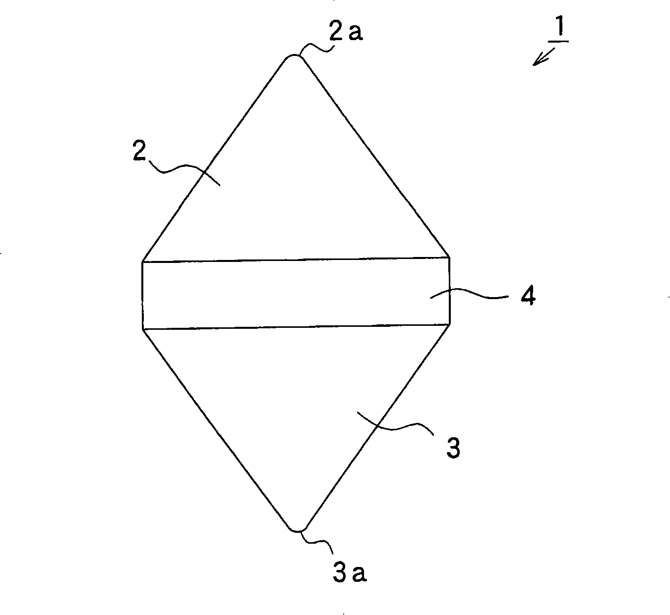
[0087] figure 1 It is a front view of the cage cone of the first embodiment of the present invention.

[0088] exist figure 1 Among them, 1 is the cone for retainer of the first embodiment of the present invention formed in a conical top shape (bacus bead shape), and 2 is the cone for retainer 1 formed in a conical shape by contracting at the upper end in the longitudinal direction toward the upper end. The upper constriction part, 2a is the top of the upper constriction part 2, 3 is the lower end constriction part of the retainer cone 1 constricted toward the lower end in the longitudinal lower end, and formed into a conical shape, 3a is the top of the lower constriction part 3, and 4 is A cylindrical middle portion is formed between the upper constriction 2 and the lower constriction 3 .

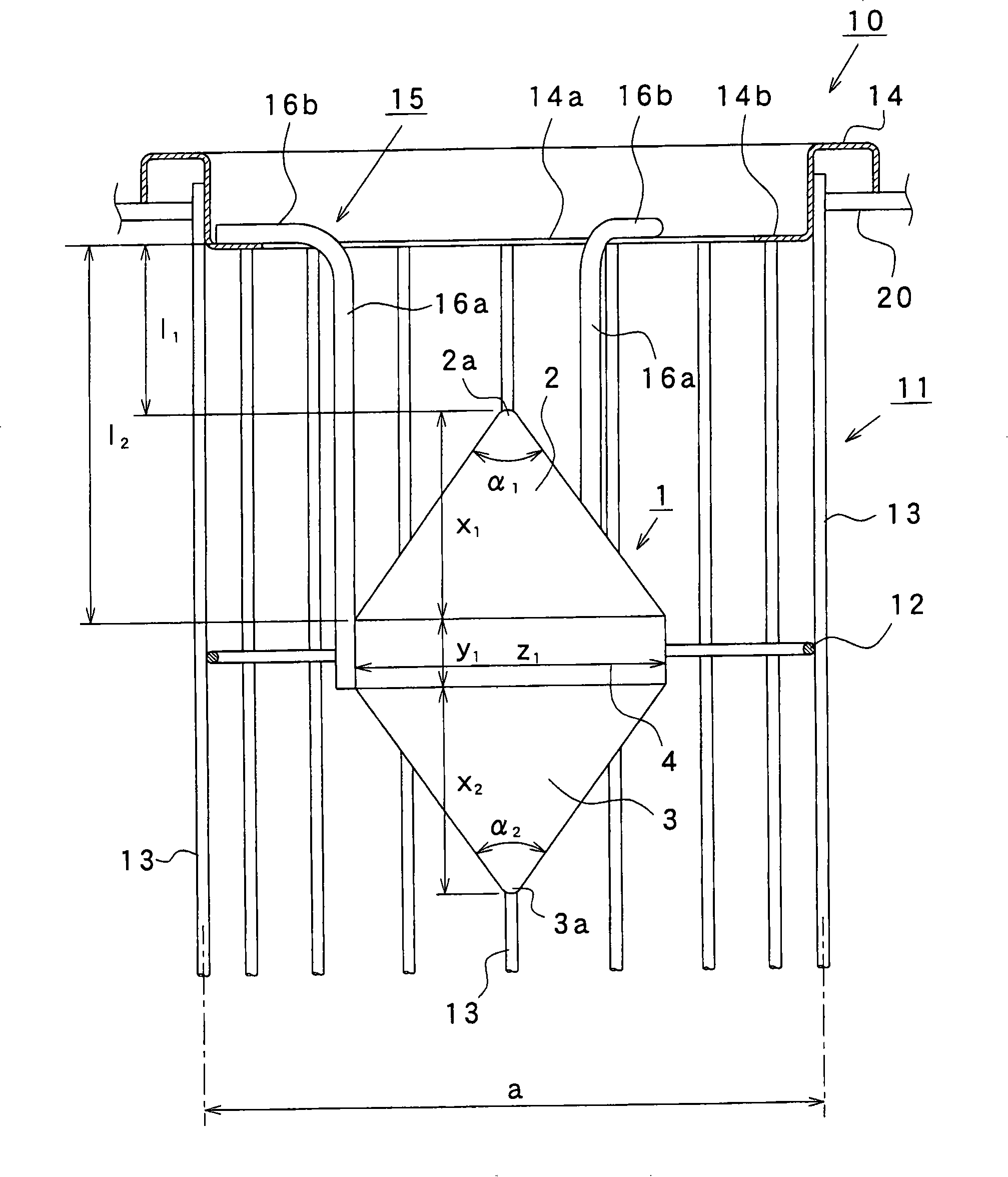
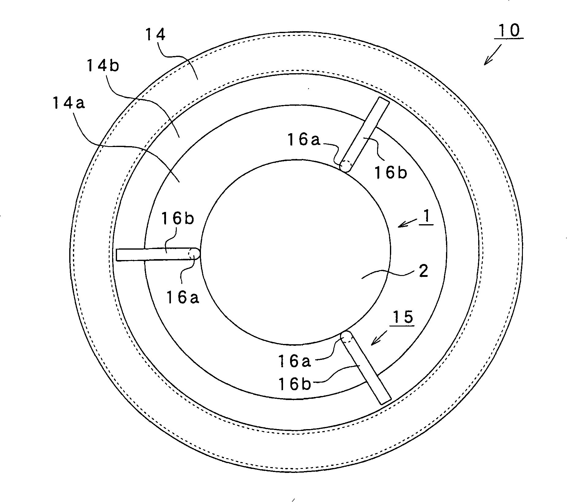
[0089] figure 2 It is a sectional front view of main parts of the bag filter holder having the holder cone according to the first embodiment of the present invention, image 3 It is a...

no. 2 approach

[0130] Fig. 6(a) is a sectional front view of main parts of a holder for a bag filter having a cone for a holder according to a second embodiment of the present invention, and Fig. 6(b) is a sectional view along line A-A of Fig. 6(a) . In addition, the same reference numerals are assigned to the same components as those in the first embodiment, and description thereof will be omitted.

[0131] In FIG. 6, the bag filter holder 10a having the holder cone of the second embodiment is different from the first embodiment in that four fixing members 15a are arranged radially at equal angular intervals on the outer periphery of the holder cone 1c. In the radial direction of the holder body 11 , it is welded to the fixing ring 12 of the holder body 11 for fixing.

[0132] If one end of the fixing member 15a is fixed on the outer periphery of the retainer cone 1c by welding or screwing, etc., the retainer cone 1c can be inserted into the holder body 11, and the other end of the fixing ...

no. 1 example

[0140] The pressure during backwashing was measured using the bag filter holder having the holder cone described in the first embodiment.

[0141] In the bag filter holder 10 used for pressure measurement, the diameter a of the holder body 11 is 160 mm, the overall length of the holder body 11 is 9000 mm, the overall length of the cone 1 for the holder is 128 mm, and the cone 1 for the holder is The angle α of the tops 2a, 3a of the upper constriction 2 and the lower constriction 3 of 1 、α 2 = 70 degrees, the diameter z of the cylindrical middle part 4 of the cone 1 for the cage 1 =80mm, the length y of the middle part of the cylinder 4 1 =18mm, installation height l from the top of the annular flange portion 14 to the upper end of the cylindrical intermediate portion 4 of the cone 1 for the holder 2 =100mm (refer to figure 2 ).

[0142] From the nozzle 30a toward the bag filter holder 10, a pulse jet (compressed air) of 294 kPa was sprayed for 0.2 seconds, and the press...


PUM


Abstract

The object of the present invention is to provide a cone for a retainer which is inserted into the center of the upper end of the retainer body which is a negative pressure generating area near the installation position of the conventional Venturi tube, so as to be effective in backwashing. When filtering cloth, a part of the compressed air sprayed from the nozzle on the upper part of the retainer body can be dispersed in the radial direction of the retainer body, preventing negative pressure from being generated on the upper end side of the retainer body, and making the entire area including the upper end side of the retainer body The filter cloth bulges outward, which can reliably dust off the dust attached to the filter cloth. Compared with the existing Venturi type, the cross-sectional area of ​​the flow path at the upper end of the retainer body can be enlarged, and dust collection can be greatly reduced. The load of the blower used for suction. The cone for the holder is inserted in the center of the upper end side of the holder body of the holder for the bag filter, and has an upper-end reduced diameter portion and a lower-end reduced diameter portion, and the upper end reduced-diameter portion faces the upper end at the upper end portion in the longitudinal direction. The reduced diameter is formed; the reduced diameter portion at the lower end is formed by reducing the diameter toward the lower end at the lower end in the longitudinal direction.

Description

technical field [0001] The present invention relates to a holder cone for a bag filter provided on a holder for a bag filter, and a holder for a bag filter having the cone for the holder, the holder for a bag filter supporting a filter cloth of a dust collector from the inside. Background technique [0002] At present, dust collectors use a device that has a filter cloth (filter bag) and a support frame (hereinafter referred to as the holder body) that allows the dust-laden air to pass through, separates and captures dust, and the support frame maintains the shape of the filter cloth. And support the filter cloth from the inside. Once the dust collector is operated, the filter cloth collects the dust, and the loss of suction force increases with the passage of the operation time, so it is necessary to intermittently or continuously shake off the collected dust. As a dust collector having such a dusting mechanism, there are pulse-jet dust collectors described in Patent Docum...

Claims


Application Information

Patent Timeline
IPC IPC(8): B01D46/02
CPCB01D46/0043B01D46/04B01D46/06B01D46/71B01D46/02
Inventor 井川英治
Owner SHINKO IND CO LTD (JP)
Why Eureka
Try Eureka