
Bidirectional spherical puncture positioner

A locator and spherical technology, used in puncture needles, medical science, surgery, etc., can solve problems such as difficulty in controlling the point and direction of puncture, affecting diagnosis and treatment effects, and deflection of the needle in soft tissue, ensuring diagnosis and Therapeutic effect, the simple structure, the effect of ensuring the accuracy

Inactive Publication Date: 2010-07-21
THE FIRST AFFILIATED HOSPITAL OF THIRD MILITARY MEDICAL UNIVERSITY OF PLA
View PDF2 Cites 0 Cited by
  • Summary
  • Abstract
  • Description
  • Claims
  • Application Information

AI Technical Summary

Problems solved by technology

In the prior art, the puncture needle is generally used for direct puncture, and the direction of the needle in the soft tissue is prone to deflection. It is difficult to control the puncture point and direction, and the number of operations increases, causing patients to suffer and reducing work efficiency
When the tissue is soft or the surface of the tissue is irregular, the operator performs puncture according to subjective experience, the above problems are more obvious, and seriously affect the diagnosis and treatment effect

Method used


Image

  • Bidirectional spherical puncture positioner
  • Bidirectional spherical puncture positioner
  • Bidirectional spherical puncture positioner

Examples


Embodiment 1

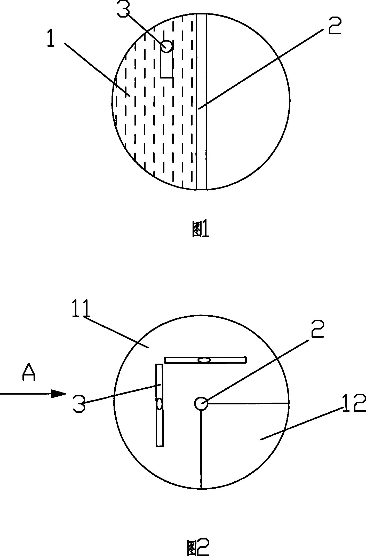
[0015] Fig. 1 is a structural cross-sectional view of Embodiment 1 of the present invention, Fig. 2 is a top view of Fig. 1, and Fig. 3 is a view along the direction A of Fig. 1, as shown in the figure: this embodiment includes a spherical base 1, and the spherical base 1 is provided with a The transparent pinhole 2 at the center of the sphere, the spherical base 1 is provided with an arc-shaped angle meter 3 for the direction indication of the transparent pinhole 2, and the arc-shaped angle meter 3 adopts the principle of a bar-type level meter, and the arc-shaped angle meter 3. The shape corresponds to the shape of the spherical base 1. The plane where the arc-shaped angle meter is located corresponds to the transparent pinhole 2, and the arc midpoint of the arc-shaped angle meter 3 corresponds to the transparent pinhole 2; the arc-shaped angle meter 3 is Two, set at an angle of 90° from the two directions of the vector axis and the coronal axis; the spherical base 1 is made ...

Embodiment 2

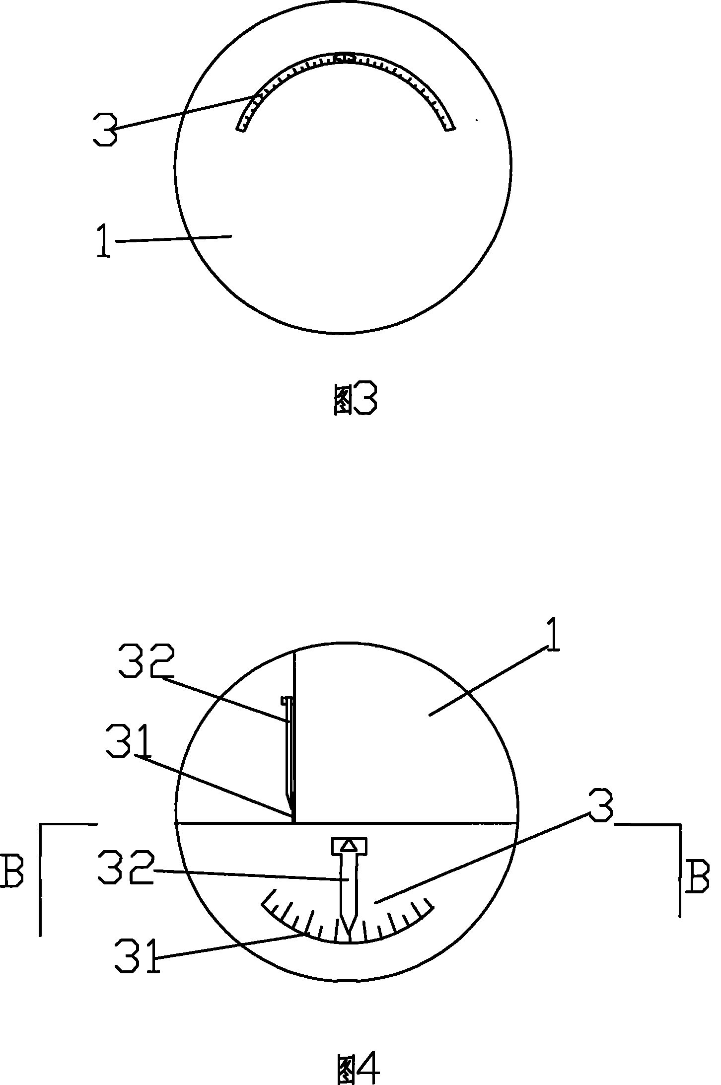
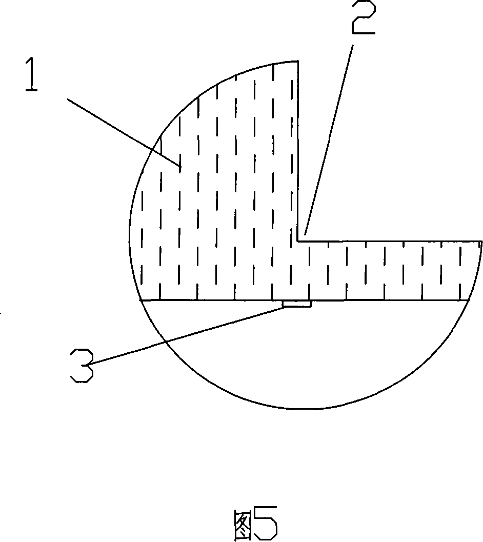
[0018] Fig. 4 is a schematic structural view of Embodiment 2 of the present invention, and Fig. 5 is a cross-sectional view along the B-B direction of Fig. 3, as shown in the figure: this embodiment includes a spherical base 1, and a longitudinal positioning groove 2 passing through the center of the sphere is arranged on the spherical base 1 for longitudinal positioning The groove 2 passes through the surface of the spherical base 1, and the cross section is fan-shaped. The spherical base 1 is provided with two orientation indicating devices 3 for longitudinally positioning the groove 2. The orientation indicating device 3 includes a dial 31 and an indicator needle 32. The spherical base 1 is transparent , two longitudinal planes with an angle of 90° are set inside, and the two planes are respectively set on the upper half and the lower half of the spherical base 1; two orientation indicating devices 3 are respectively set on the two planes, and the pointer 32 indicates The en...


PUM


Abstract

The present invention discloses a bidirectional orbicular puncture localizer, comprising an orbicular matrix which is provided with a positioning hole or a slot which passes through a ball center. According to the characteristic that the orbicular matrix can be put or embedded inside the irregular position, the present invention can be used for positioning when the quite soft tissue and the irregular tissue are punctured. The orbicular matrix is provided with the positioning hole or slot, which is convenient for using. A needle penetrating hole or a slot can fix a puncture needle at the head,the feet and the left and right directions during the process of puncturing to avoid the directional deviation.

Description

technical field [0001] The invention relates to a puncture medical device, in particular to a bidirectional spherical puncture positioner. Background technique [0002] Puncture is a means of biopsy and disease treatment. For example, percutaneous biopsy is to reach the lesion area for biopsy and particle implantation through percutaneous puncture, and it is to reach the lesion area for treatment through percutaneous puncture. On the one hand, it is used for the diagnosis of diseases, and on the other hand, it injects drugs and places instruments through puncture for treatment. During the puncture process, the puncture needle is used to penetrate into the diseased tissue for collecting specimens and establishing a working channel. In the prior art, puncture needles are generally used for direct puncture, which is prone to deflection of the needle direction in the soft tissue. It is difficult to control the puncture point and direction, and the number of operations increases...

Claims


Application Information

Patent Timeline
Patent Type & Authority Patents(China)
IPC IPC(8): A61B17/34A61B19/00
Inventor 黄学全陈伟蔡萍
Owner THE FIRST AFFILIATED HOSPITAL OF THIRD MILITARY MEDICAL UNIVERSITY OF PLA
Learn More