Spherical hinge type joint electric locking device

A technology of locking device and ball joint, which is applied in the direction of joints, manipulators, manufacturing tools, etc., can solve the problems of manual locking, etc., and achieve the effect of reliable loosening and locking, large braking torque and good flexibility

Inactive Publication Date: 2008-07-09
BEIHANG UNIV
View PDF0 Cites 11 Cited by
  • Summary
  • Abstract
  • Description
  • Claims
  • Application Information

AI Technical Summary

Problems solved by technology

[0004] The object of the present invention is to provide an electric locking device for ball joints, especially a joint structure with reliable loosening and locking, so as to solve the problem that ball joints need to be manually locked in the prior art, and give full play to The characteristics of the high flexibility of the ball joint

Method used


Image

  • Spherical hinge type joint electric locking device
  • Spherical hinge type joint electric locking device
  • Spherical hinge type joint electric locking device

Examples


Embodiment Construction

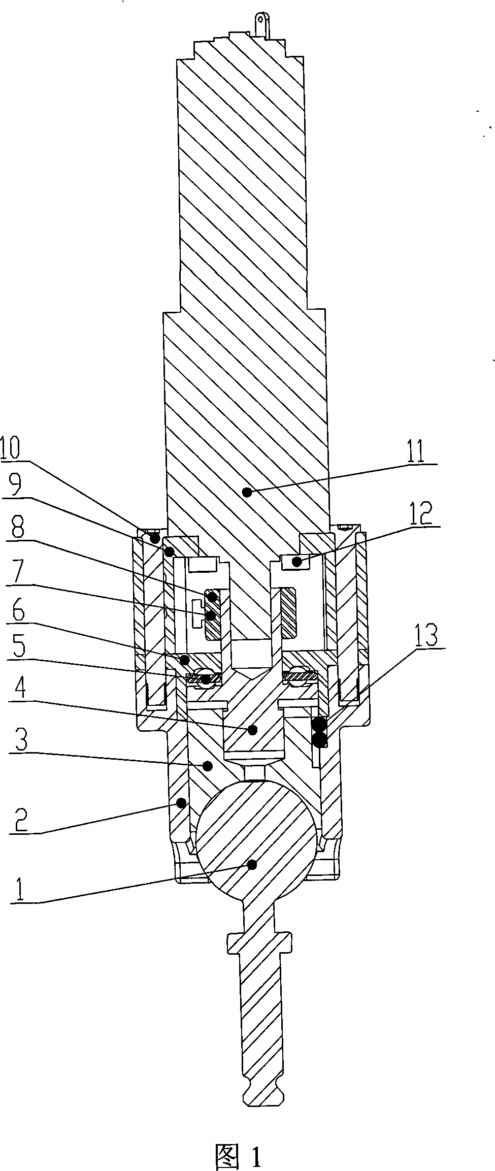
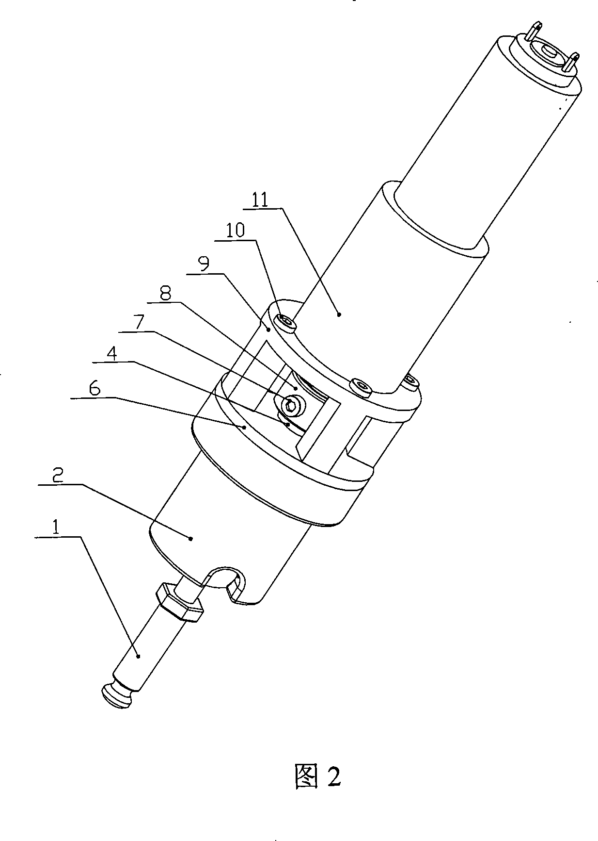
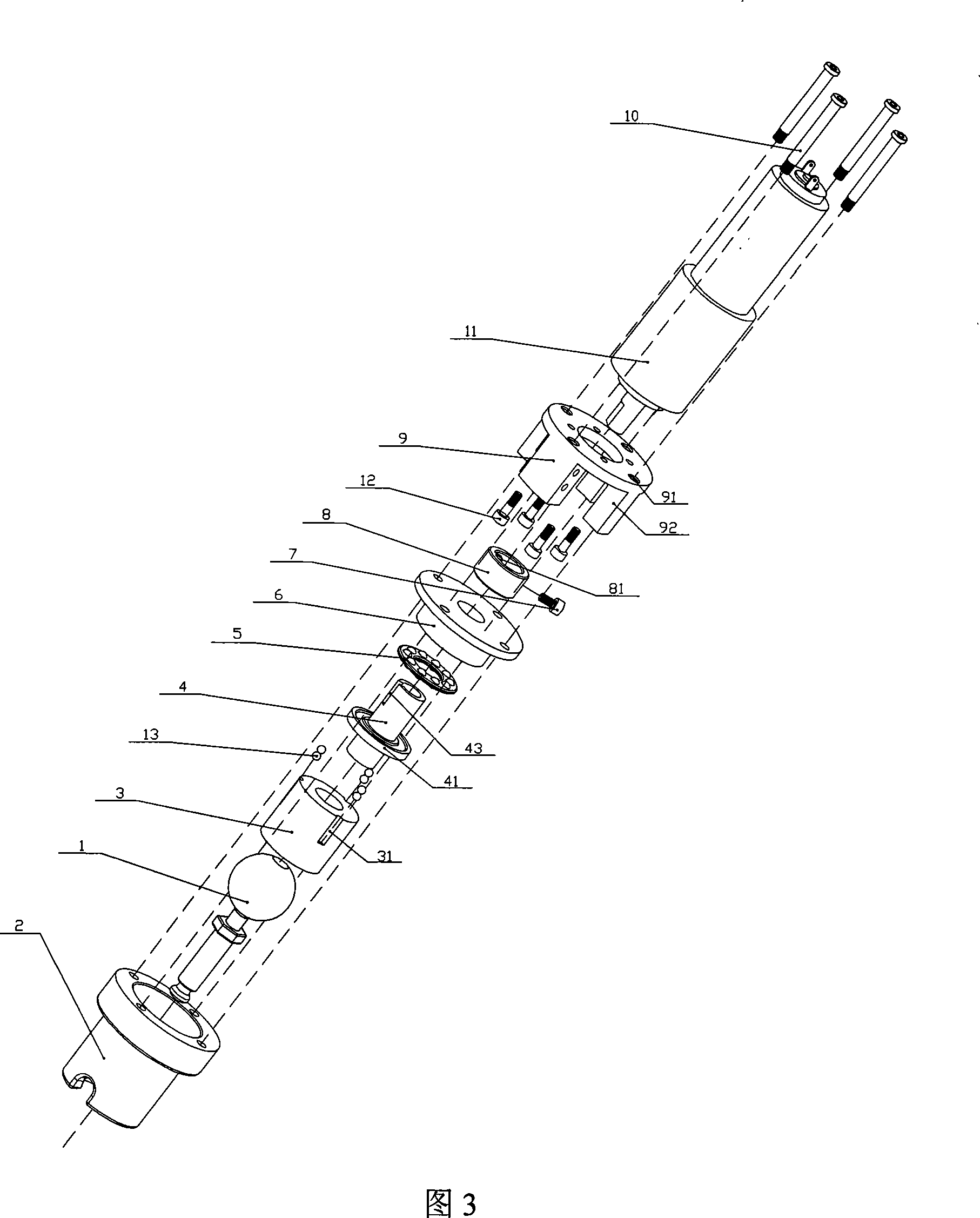
[0032] A spherical joint electric locking device of the present invention, please refer to Fig. 1 to Fig. 5, which includes:

[0033] A ball head rod 1, one end of which is a spherical round head, and one end is a cylindrical rod;

[0034] A ball joint seat 2 is a cylinder with a round hole in the middle; one end is in the shape of an inner spherical surface, which is matched with the spherical round head of the ball head rod; there are semicircular grooves (not shown in the figure) evenly distributed on the upper side of the inner wall;

[0035] A push ball shoe 3 is a cylinder with a concave spherical surface dug at one end, and semicircular grooves 31 uniformly distributed on the outer edge thereof, which cooperate with the semicircular grooves on the inner wall of the ball joint seat to form round holes for installing balls;

[0036] A threaded shaft 4 is a cylinder with a ring 41 protruding from the middle; a circular hole 42 is drilled on its upper part and a keyway 43 i...


PUM


Abstract

The present invention relates to an electric locking device of a spherical hinge type joint, which comprises a ball rod, a spherical joint seat, a ball-thrusting tile, a threaded shaft, a ball support ring, an antithrust end closure, a key ring, a motor seat, a direct current speed-down motor, etc. The ball rod is installed on the bottom of the spherical joint seat, the ball-thrusting tile is intalled in the spherical joint seat and press the ball head of the ball rod, a ball is installed in a cylindrical hole formed by the semicircular groove of the ball-thrusting tile and the semicircular groove of the spherical joint seat, the threaded shaft is suitably installed in the ball-thrusting tile via a triangular external thread, the ball support ring is installed on the threaded shaft, the antithrust end closure fastens the threaded shaft and the ball support ring on the spherical joint seat, the key ring is fastened in the key slot of the threaded shaft, the direct current speed-down motor is installed on the motor seat by motor-fixing bolts, the motor seat is tightly connected with the spherical joint seat by trip bolts, and then key ring bolts are installed on the key ring. Widely applicable to mechanical arms and robots, the device has the advantages of good flexibility, simple structure, reliable unlocking and locking and great brake torque.

Description

(1) Technical field: [0001] The invention provides a spherical joint electric locking device, which is especially suitable for man-machine cooperation (also known as passive) mechanical arm and robot joint design, and belongs to the field of robot structure design. (two) background technology: [0002] Man-machine cooperative (also known as passive) robotic arm refers to a robotic arm that does not have active movement capabilities, that is, there is no driving device for each joint of the robotic arm, and its motion posture and position are completely determined by the operator. When the required posture or position is reached , it can be locked and maintained according to the command and can withstand a certain external force. [0003] The spherical joint has 3 degrees of freedom, so its flexibility is very good. It is a very good choice for the man-machine cooperation manipulator that requires high flexibility. However, in general applications, the spherical joint is manu...

Claims


Application Information

Patent Timeline
Patent Type & Authority Applications(China)
IPC IPC(8): B25J17/00B25J19/00F16C11/10
Inventor 刘荣余静科张建伟李简王峰
Owner BEIHANG UNIV
Why Eureka
Try Eureka