Floor and ceiling fixing device

A technology for fixing devices and ceilings, applied to floors, building components, buildings, etc., can solve problems such as loss of site costs, adverse effects of business opening time, and operational obstacles, and achieve reduced work intensity, good locking effect, and easy maintenance. Effect

Inactive Publication Date: 2008-07-09
王君
View PDF0 Cites 11 Cited by
  • Summary
  • Abstract
  • Description
  • Claims
  • Application Information

AI Technical Summary

Problems solved by technology

resulting in large operating losses
The replacement of the office decoration in the commercial building will also hinder the operation of the original enterprise, and even have to stop some work
For newly moved companies, the complicated decoration process will have a negative impact on the opening time of the company, and will also cause a corresponding loss of site costs

Method used


Image

  • Floor and ceiling fixing device
  • Floor and ceiling fixing device
  • Floor and ceiling fixing device

Examples


Embodiment 1

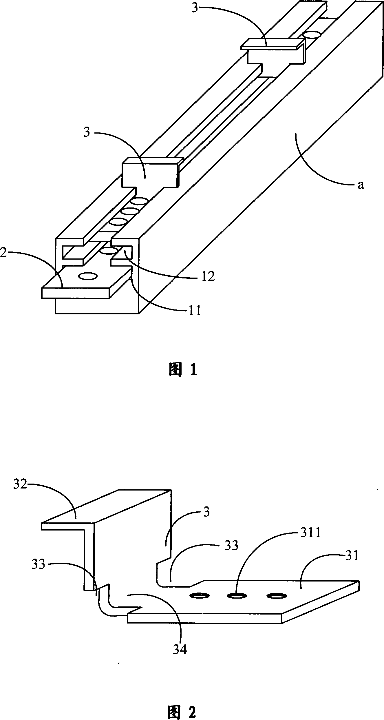
[0058] Figure 1 shows a specific embodiment of the present invention, including a beam a for carrying the floor or ceiling. multi-layer chute group. Both the lower floor chute 11 and the upper floor chute 12 are linear chutes whose inner width dimension is greater than the notch width dimension. The notch of the lower floor chute 11 is located at the bottom of the upper floor chute 12 . The lower chute group is provided with a sliding piece 2 matching the lower chute 11, and the sliding piece 2 is provided with a plurality of screw holes and bolts. When the bolt passes through the screw hole on the slide 2 and is tightened, the end of the bolt touches the bottom of the lower chute 11, and the slide 2 can be fixed. When the bolt is loosened, the slide 2 can be placed in the lower chute. Swipe any of the 11.

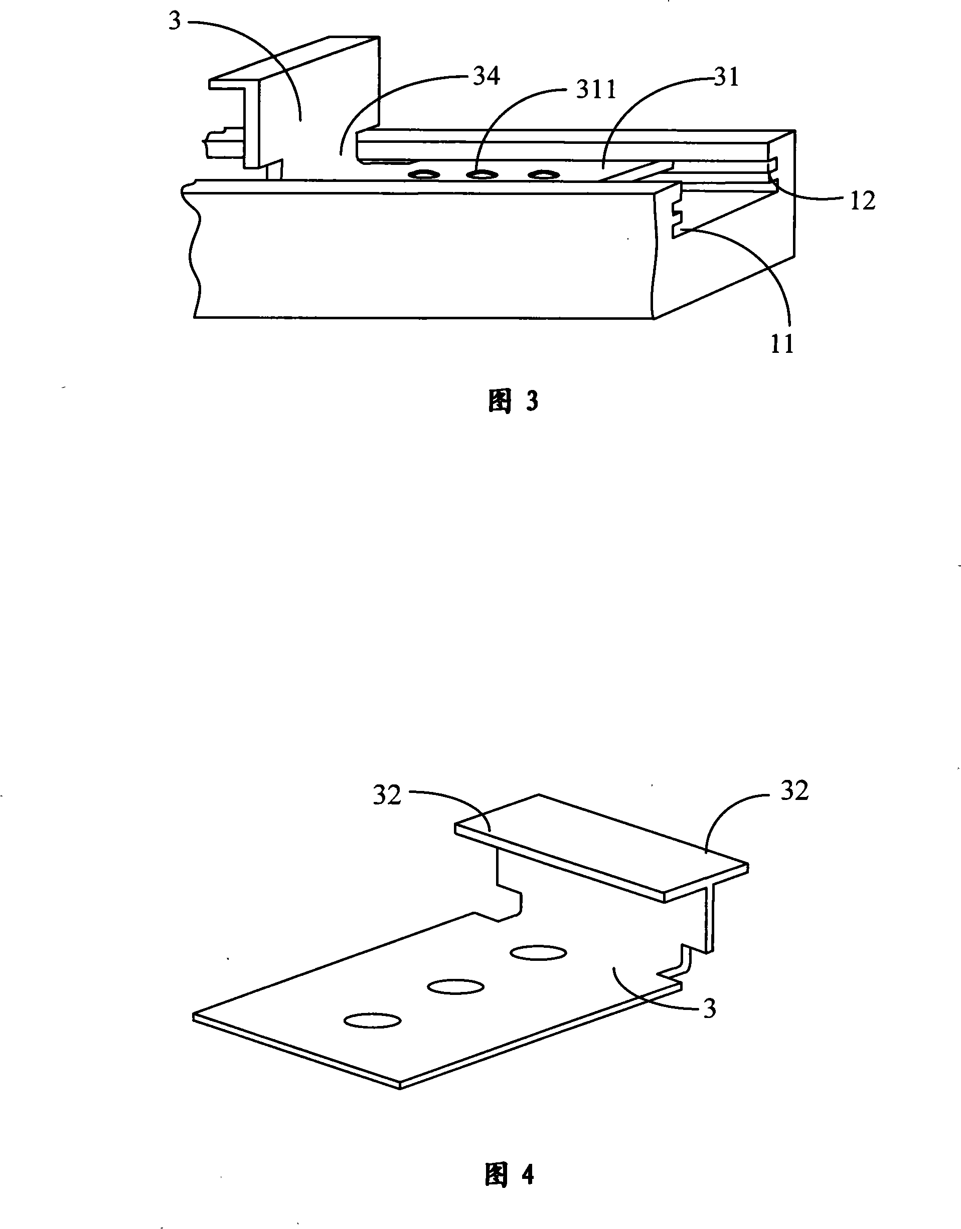
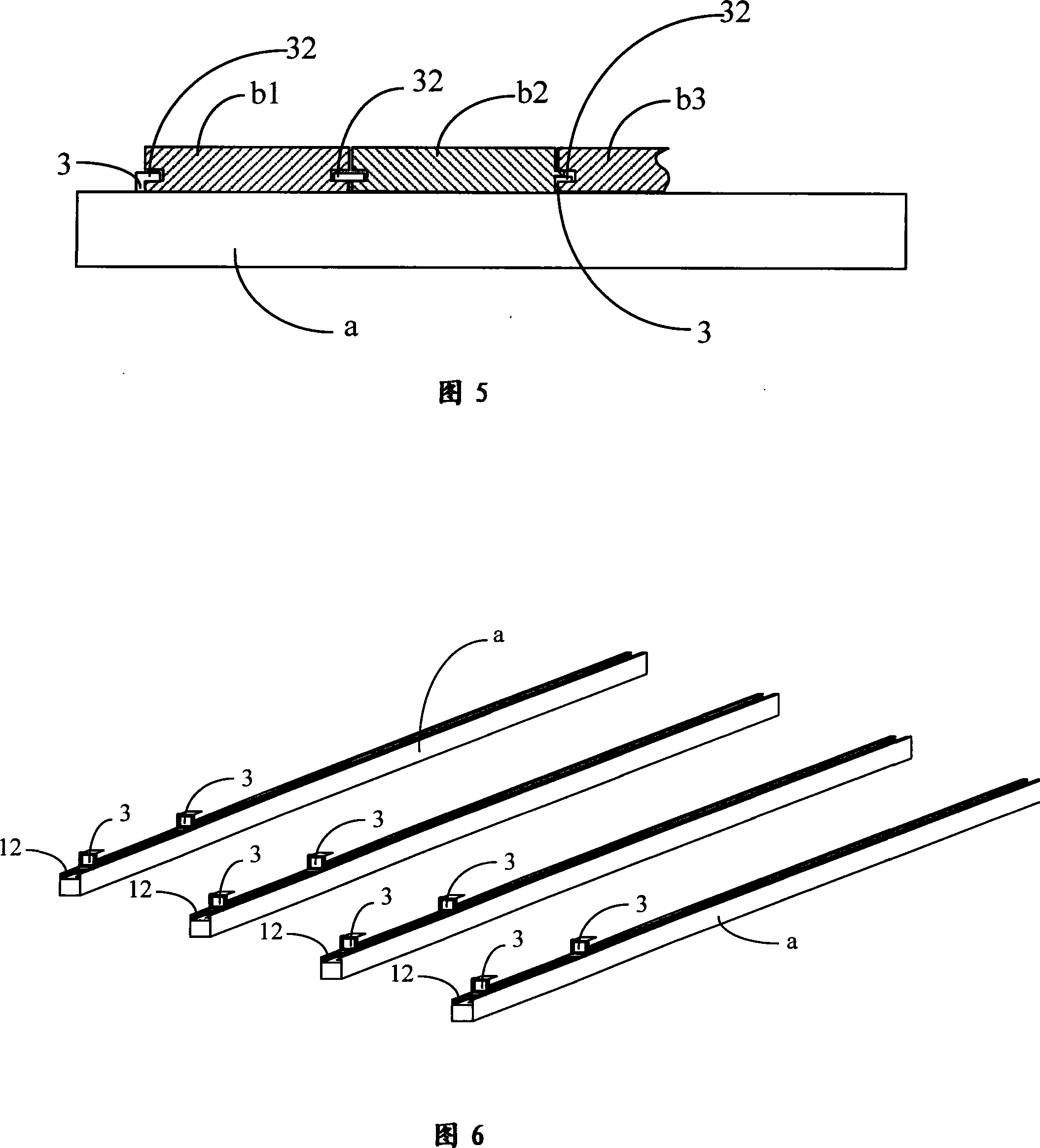
[0059] A bending fixed plate 3 is provided for moving in the upper chute 11 . The structure and arrangement of the bent fixing plate 3 are shown in Fig. 2 and Fig. 3 ....

Embodiment 2

[0066] Fig. 8 shows another specific embodiment of the present invention. In the figure, the beam a is composed of a plurality of chute positioning connecting rods 1 axially connected end to end, and the chute positioning connecting rod 1 is a cylindrical body. The connection between the adjacent chute positioning connecting rods 1 is realized by the sliding piece 2 provided in the lower chute 11 . The structure of the chute positioning connecting rod 1 is shown in FIG. 9 . In the figure, the structure of the chute positioning connecting rod 1 is the same as the beam in the first embodiment, and has a lower chute 11 and an upper chute 12 . The upper chute 12 is mainly used for setting the bent fixing plate and carrying the floor or ceiling. The connection method between the chute positioning connecting rods 1 is as follows: set the two ends of a sliding piece 2 in the lower chute 11 of two adjacent chute positioning connecting rods 1, and then tighten the bolts in the screw h...


PUM


Abstract

The invention relates to a fixing device of floors and ceilings, which comprises a bridging beam, wherein the bridging beam is a column body, the upper surface is provided with a lower layer sliding groove and an upper layer sliding groove, the lower layer sliding groove and the upper layer sliding groove are both straight line-shaped sliding groove whose inner width size is larger than the width size of the groove mouth, the lower layer sliding groove is provided with a sliding slab, a plurality of screw holes and screw bolts are arranged on the sliding slab, a flexing mounting slab is arranged in the upper layer sliding groove, one end of the flexing mounting slab is a moving end, the shape of the moving end is matched with the section shape of the upper layer sliding groove, the other end of the flexing mounting slab is a locking end, and a screw hole is opened on the moving end. The invention changed the traditional structure and the construction technique of floors and ceilings, the scene has no dust, no noise and no peculiar smell, the invention has the advantages of quick assembly and disassembly, the size of each item can be flexibly adjusted, the concealed work which is arranged on the ceiling or under the floor realizes open, and the technical shortcoming which exists in the existing finishing construction method can be overcome.

Description

technical field [0001] The invention relates to a floor and ceiling fixing device, in particular to a fast installation and removal fixing device capable of flexibly adjusting the position and fixing each floor and ceiling. Background technique [0002] Traditional interior decoration technology is often affected by civil engineering technology, which not only requires a long renovation period, but also produces more garbage, noise, and dust, which will cause greater damage and impact on the surrounding environment. As far as the traditional ground decoration treatment method is concerned, no matter laying the floor, or stone or ceramic tile, it is first necessary to carry out construction treatment on the ground surface (remove the leftover decoration in the past or lay cement for ground leveling treatment). This just needs to transport in a large amount of materials (as cement, sandstone and lime etc.), also will transport out a large amount of waste materials simultaneous...

Claims


Application Information

Patent Timeline
Patent Type & Authority Applications(China)
IPC IPC(8): E04B9/06E04F15/02
Inventor 王君
Owner 王君
Why Eureka
Try Eureka