
Rapid water heater

A water heater, fast technology, applied in water heaters, fluid heaters, lighting and heating equipment, etc., can solve the problems of uneven heating of the transducer plate, unreasonable connection, insufficient contact, etc., to achieve good heat dissipation, The effect of sufficient space utilization and sufficient heating

Inactive Publication Date: 2008-07-09
SUPERMAN GROUP
View PDF1 Cites 7 Cited by
  • Summary
  • Abstract
  • Description
  • Claims
  • Application Information

AI Technical Summary

Problems solved by technology

[0011] The technical problem to be solved and the technical task proposed by the present invention are to overcome the defects of the prior art that the energy-transfer sheet is extremely unevenly heated, and the dead water area is easily formed in the water tank to form fouling, and to provide an eddy current heating device (i.e. Transducer sheet) is an electromagnetic induction heating instant water heater with uniform heating everywhere and no dead water area in the water tank, and on this basis, it further overcomes the insufficient contact between the transducer sheet of the water heater in the prior art and the water flow flowing through the water tank. There are no cooling systems on the device, and the connection between the two water tanks is not reasonable, etc.

Method used


Image

  • Rapid water heater
  • Rapid water heater
  • Rapid water heater

Examples


Embodiment 1

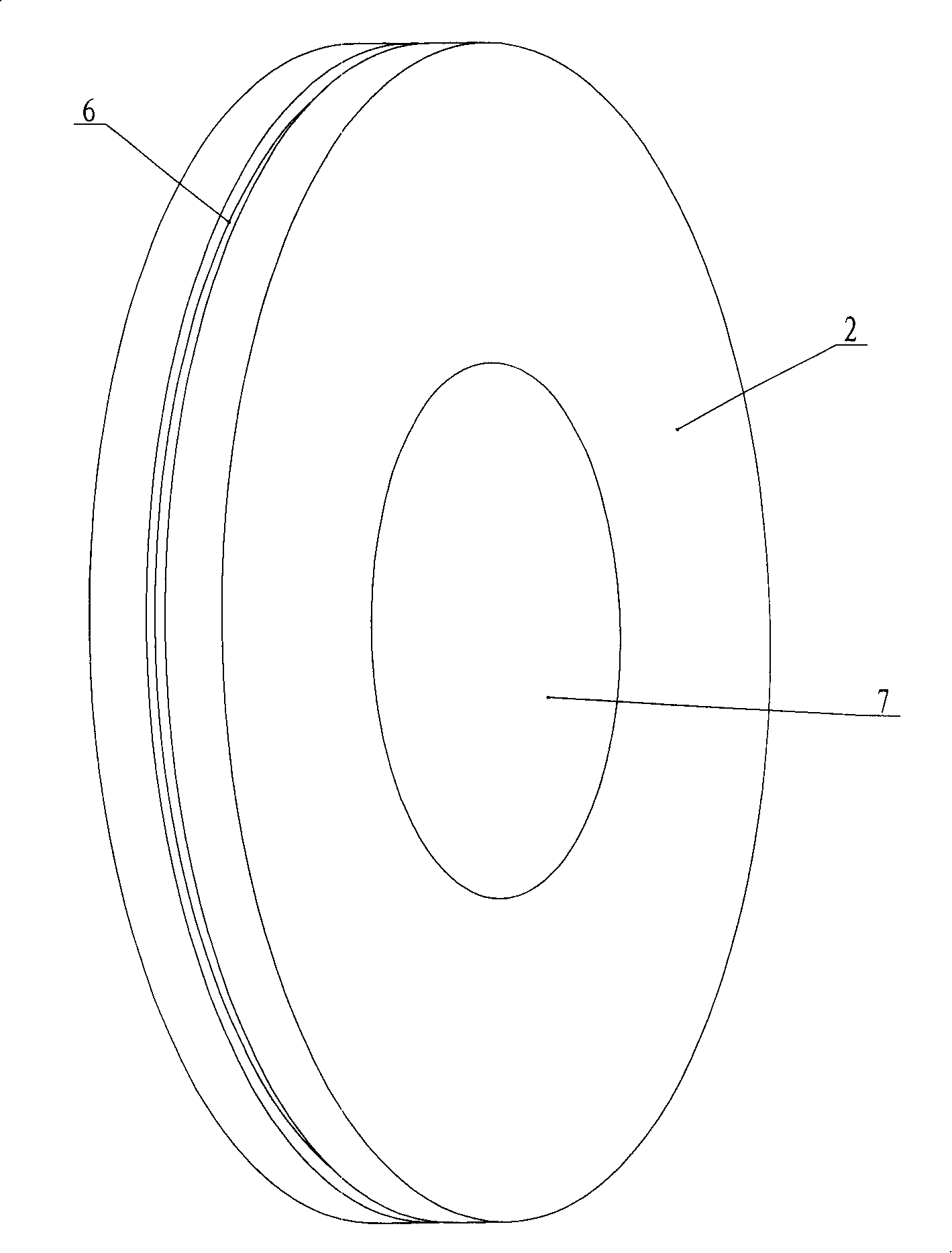
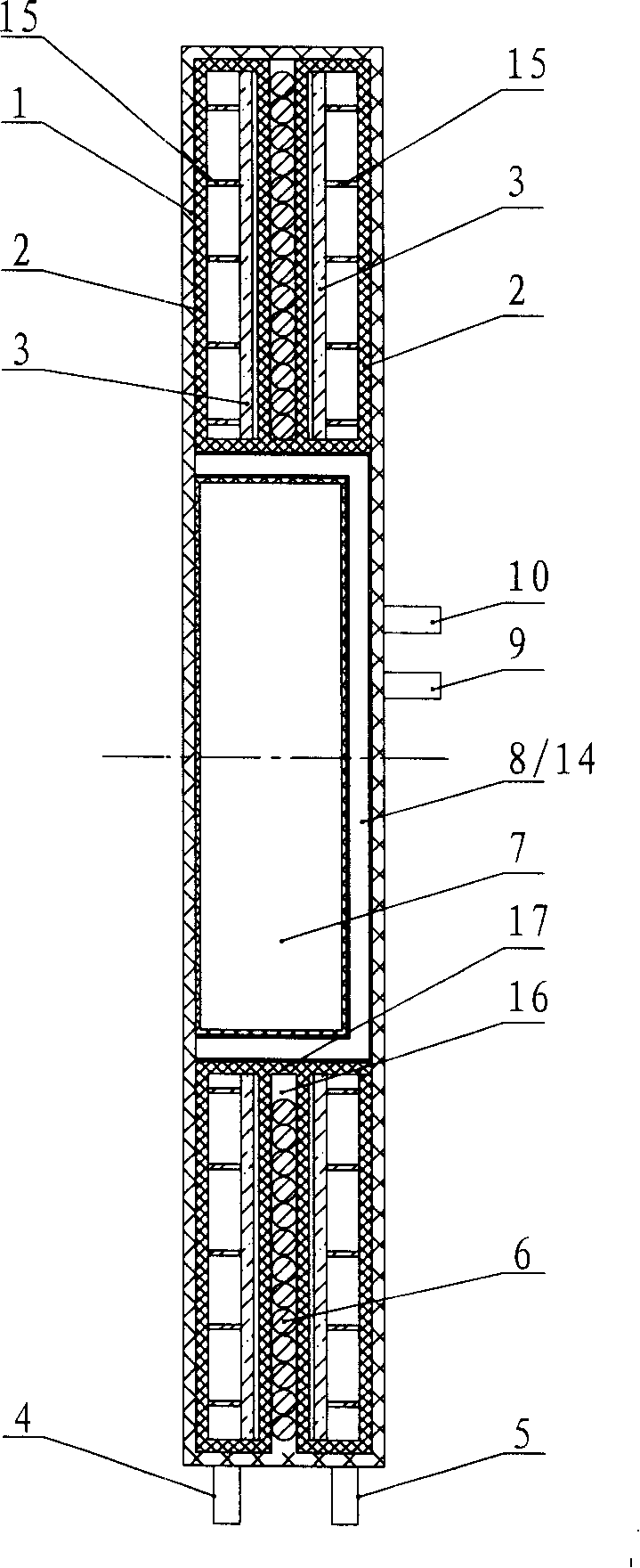
[0042] figure 1 and figure 2 The electromagnetic induction heating instant water heater shown includes a housing 1 and a water tank 2 arranged in the housing 1, a heating coil 6 and a power frequency converter 7. The water tank 2 is provided with a water inlet pipe 4 and a water outlet pipe 5. The water tank 2 is provided with an eddy current heating device, and the heating coil 6 is electrically connected to the power frequency converter 7; more specifically:

[0043] The water tank 2 , the eddy current heating element and the heating coil 6 are annular, and the heating coil 6 is located outside the water tank 2 and arranged corresponding to the eddy current heating element.

[0044] An accommodating cavity 14 is formed at the center of the water tank 2, and the accommodating cavity 14 is formed by setting an annular support portion 17 between two water tanks. Inside.

[0045] The accommodation cavity 14 is a closed cavity, and a cooling water inlet 9 and a cooling water...

Embodiment 2

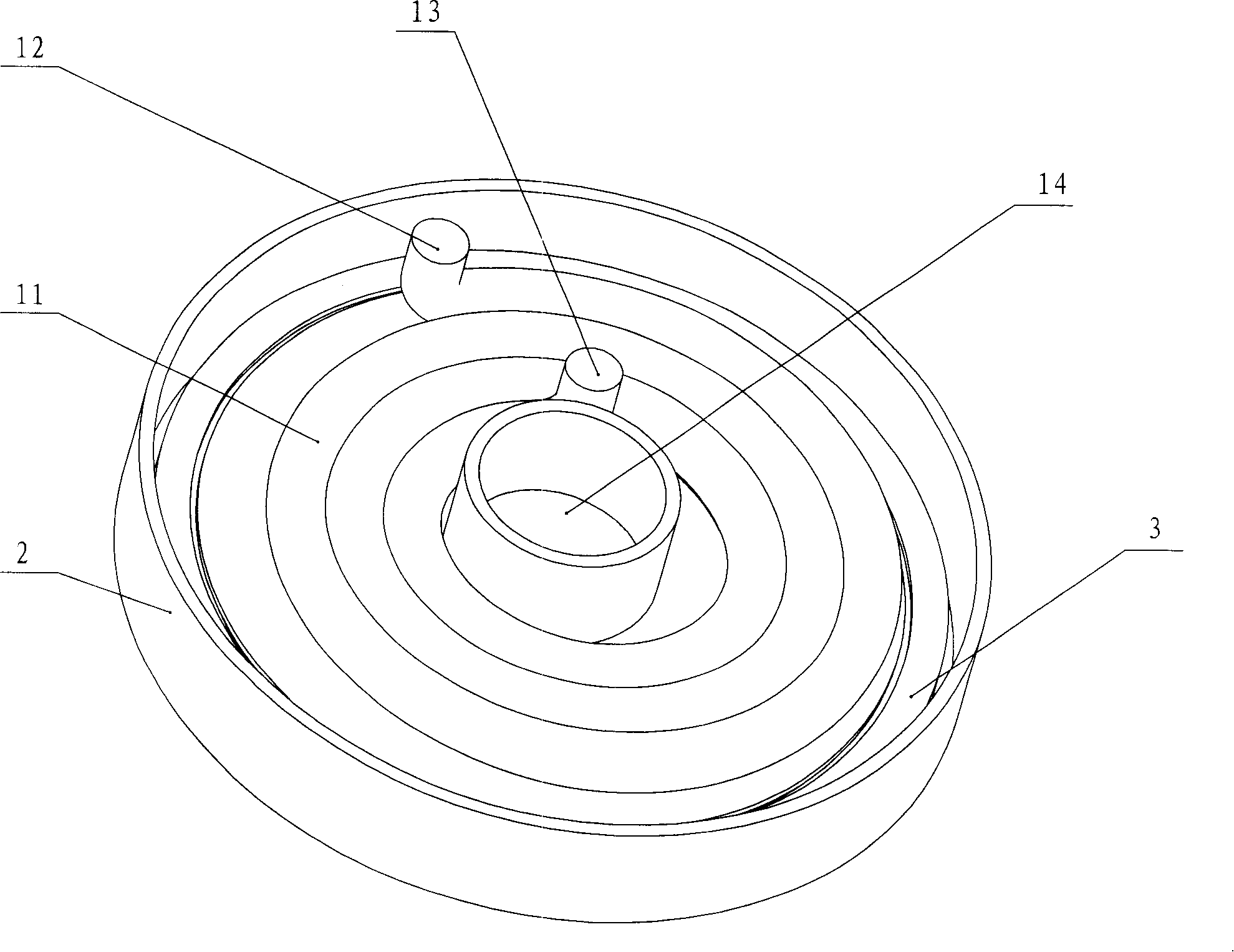
[0056] Such as image 3 As shown, the eddy current heating device includes a flat annular sheet 3 and a heat conducting spiral coil 11 in thermal contact with the flat annular sheet 3 to enhance the heat exchange effect. One end 12 of the heat-conducting spiral coil 11 is connected with the water outlet pipe 5, and the other end is led to the outside of the water tank 2 through 13 as a hot water outlet, so as to prolong the residence time of the water flow in the water tank 2 and fully exchange heat (see Fig. 4 ( c), 4(d)); or one end 12 of the heat-conducting spiral tube 11 is connected to the cooling water outlet 10, and the other end is opened in the water tank 2, so that the cooling water can be led to the water tank to make all the water flow in the water tank flow to prevent the formation of dead water areas; in order to enhance the heat transfer effect, the heat-conducting spiral coil 11 is made of water pipes with excellent thermal conductivity such as copper water pip...


PUM


Abstract

A quick water heater belongs to heating equipment and solves the problems of prior art, such as non-uniform heating of energy-converting sheets, formation of stagnant water zones in the water tank, and scale formation. The quick water heater comprises a shell inside which a water tank, a heating coil and a power frequency transformer are arranged, an eddy current heating device arranged inside the water tank, and a water inlet pipe and a water outlet pipe both arranged on the water tank. The heating coil is eclectically connected with the power frequency transformer. The invention is characterized in that the water tank, the eddy current heating device and the heating coil are ring-shaped; and the heating coil is positioned outside the water tank and opposite to the eddy current heating device. The inventive technical proposal ensures the uniform distribution of heat produced by the eddy current heating device and the uniform heating of water flowing through the heating device, thereby increasing the heat efficiency of the water heater. Additionally, the ring-shaped water tank can prevent the formation of stagnant water zones and water scale, so that the service performance of the water heater is improved and the service life of the water heater is prolonged.

Description

technical field [0001] The invention belongs to a heating device, in particular to an instant water heater adopting electromagnetic induction heating technology. Background technique [0002] The utility model patent with the patent number ZL03250187.0 discloses a technical solution of "electromagnetic fast water heater". Figure 6 and Figure 7 Shown the structure of this prior art instant water heater, its water tank 2 (A) is two parallel rectangular tanks, communicates with each other and forms with water inlet pipe 4 (A) and water outlet pipe 5 (A). Transducer sheet 3 (A) is all housed in each rectangular tank. A circular heating coil 6 (A) is arranged between the two rectangular water tanks. The heating coil 6 (A) is driven by the power frequency converter control circuit 7 (A). When a high-frequency alternating current passes through the heating coil 6 (A) , the transducer 3(A) in the rectangular water tank will generate eddy current and generate heat due to electrom...

Claims


Application Information

Patent Timeline
Patent Type & Authority Applications(China)
IPC IPC(8): F24H1/20
Inventor 应平祥
Owner SUPERMAN GROUP
Learn More