Display apparatus and its optical film preparation method

A display device and optical film technology, applied in optics, identification devices, nonlinear optics, etc., can solve the problems that do not conform to the development trend of increasingly thin and light liquid crystal display devices, and the structure and process are complicated, and achieve auxiliary luminous intensity, enhance light Use rate, improve the effect of excessive thickness

Inactive Publication Date: 2008-07-09
AU OPTRONICS CORP
View PDF0 Cites 6 Cited by
  • Summary
  • Abstract
  • Description
  • Claims
  • Application Information

AI Technical Summary

Problems solved by technology

[0004] Although the above reflective polarized brightness enhancement film technology can achieve the effect of brightness enhancement, its structure and process are complicated. For example, its placement is limited to the setting between the backlight module and the polarizer, and usual

Method used


Image

  • Display apparatus and its optical film preparation method
  • Display apparatus and its optical film preparation method
  • Display apparatus and its optical film preparation method

Examples


no. 1 example

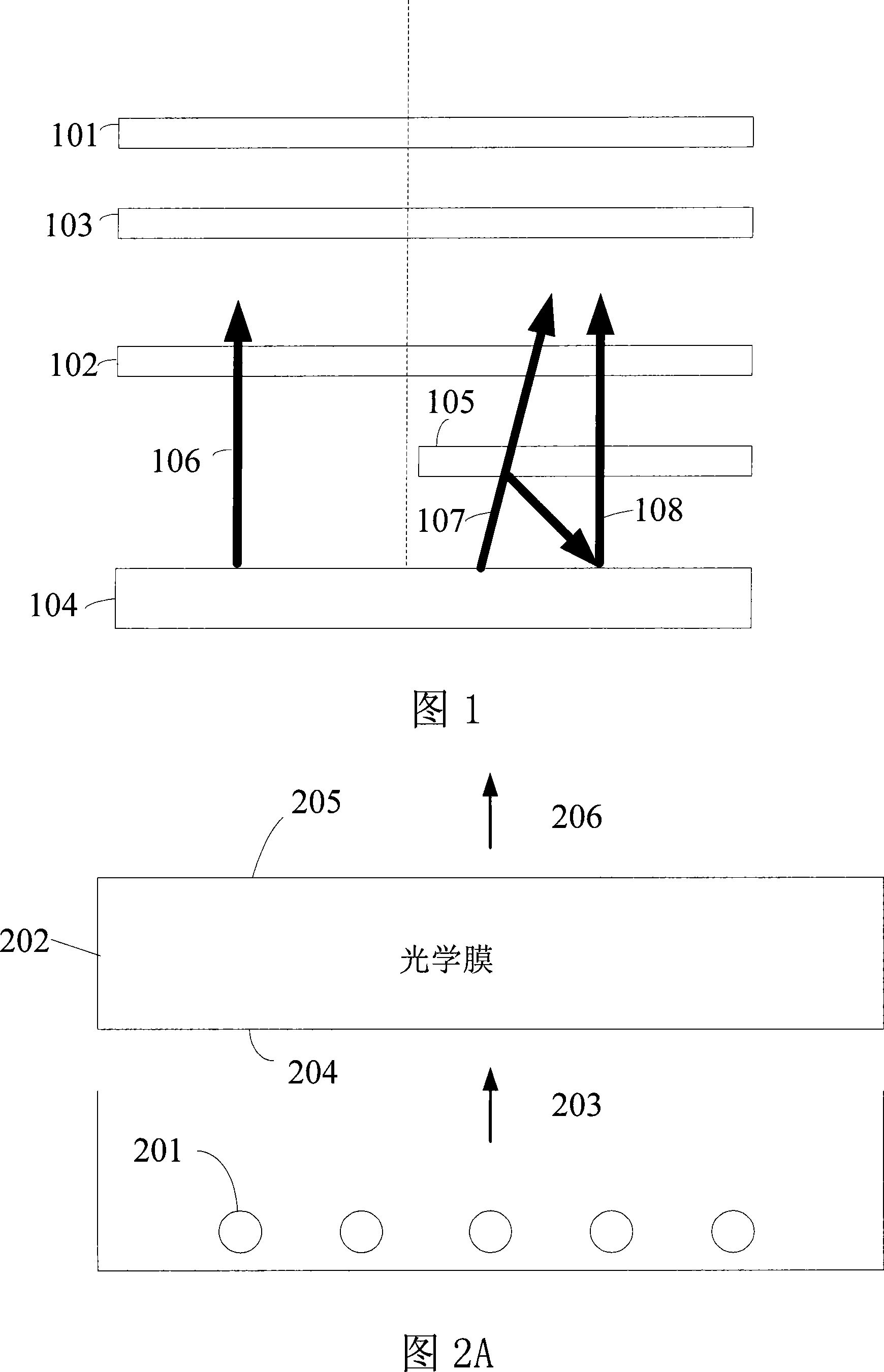
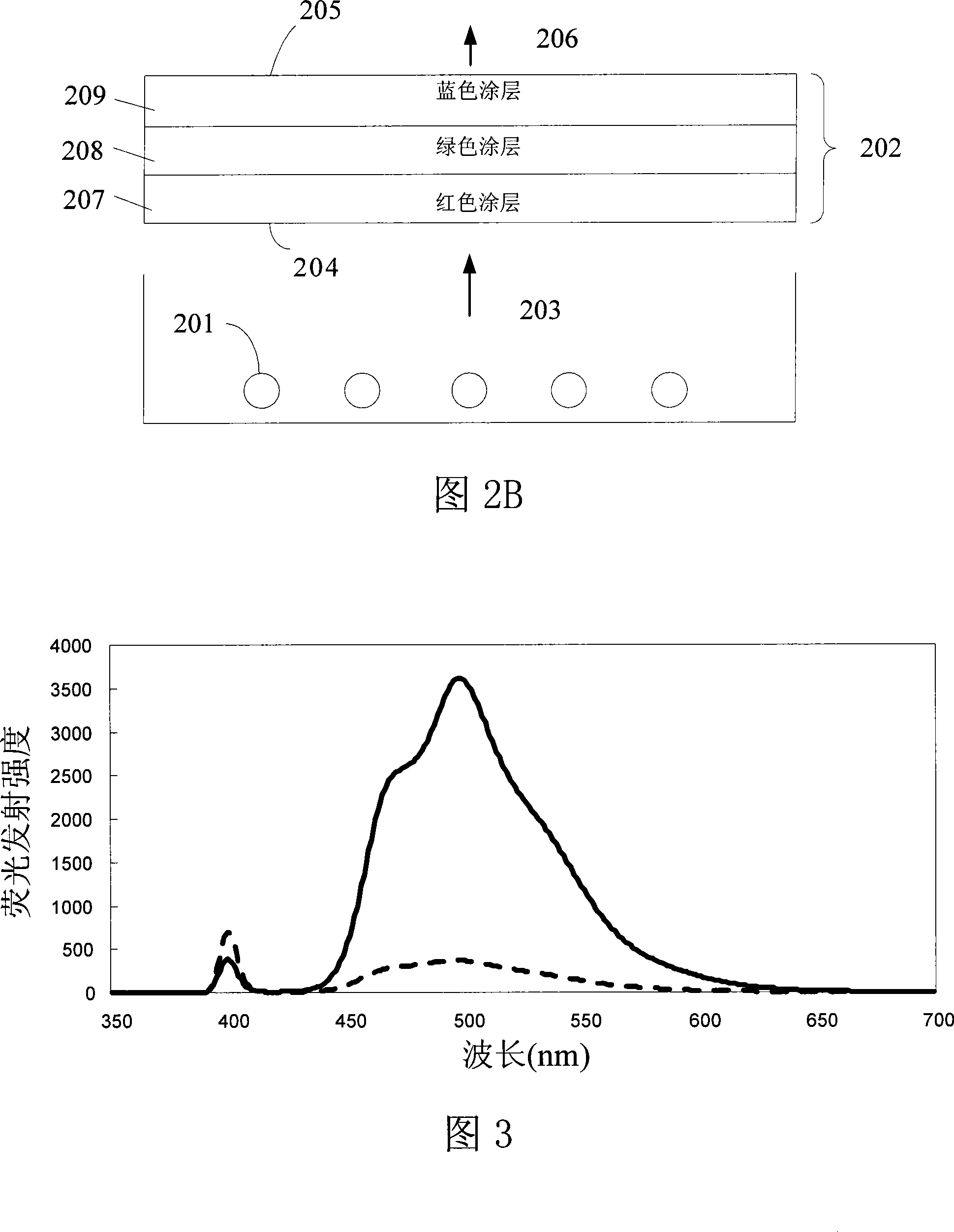
[0033] FIG. 2A depicts a first embodiment of the present invention, which is an optical film 202 and a backlight module for a display device. The display device includes a light source 201 and an optical film 202 in a backlight module. The light source 201 provides a first light 203 to the optical film 202 . The light source of the backlight module can be a direct light source, as shown in FIG. 2A , or an edge light source with a light guide plate. The structure of the optical film 202 includes at least one coating layer having a first surface 204 and a second surface 205 opposite to the first surface. One of the features of the present invention is that the coating of the optical film 202 is adapted to absorb the first light 203 emitted from the light source 201 from the first surface 204 , and stimulate a second light 206 to emit from the second surface 205 . In particular, the intensity of the second light 206 is greater than that of the first light 203 to assist the back...


PUM


Abstract

The invention provides a display device and a manufacture method of the optical film of the display device. The display device at least comprises a light source and an optical film, wherein the light source is used for providing a first light beam to the optical film, and the optical film contains at least one coating. The coating includes a first surface and a second surface opposite to the first one, and is used for absorbing the first light beam through the first surface and emitting a second light beam under excitation to the outside through the second surface, wherein the intensity of the second light beam is larger than the intensity of the first light beam. The invention can overcome the disadvantage of overlarge thickness of a brightness enhancement film of the display panel in prior art, simplify the complex process of prior art, assist the backlight source in improving light emission intensity and improve the light utilization rate of the display device.

Description

technical field [0001] The invention relates to a display device and a manufacturing method thereof, in particular to an optical film applied in a display device and a manufacturing method thereof. Background technique [0002] In the current liquid crystal display device, there is usually a brightness enhancement film, and its main function is to improve the luminous brightness and efficiency of the liquid crystal display device. The brightness enhancement films of the prior art all use the backlight module as the light source. The principle is to add a reflective optical film to the backlight module of the prior art, so that part of the light generated by the backlight module can be recycled after secondary reflection. Further, the light utilization rate of the backlight module is improved. At present, the main common brightness enhancement films include prism type brightness enhancement film, reflective polarized brightness enhancement film, cholesteric liquid crystal re...

Claims


Application Information

Patent Timeline
IPC IPC(8): G02F1/13357G02F1/136G02F1/1333G09F9/35G02F1/1335
Inventor 郑岳世叶碧纯胡至仁甘丰源
Owner AU OPTRONICS CORP
Why Eureka
Try Eureka