A testing device and method with passive optical network optical line terminal

An optical line terminal and passive optical network technology, which is applied in the field of testing devices for passive optical network optical line terminals, can solve the problems of complicated wiring ONU/ONT control, etc., and achieve the effect of easy operation and use and simple realization.

Active Publication Date: 2008-07-09
ZTE CORP
View PDF0 Cites 7 Cited by
  • Summary
  • Abstract
  • Description
  • Claims
  • Application Information

AI Technical Summary

Problems solved by technology

When the number of connected ONU/ONT is large or even fully configure

Method used


Image

  • A testing device and method with passive optical network optical line terminal
  • A testing device and method with passive optical network optical line terminal

Examples


Example Embodiment

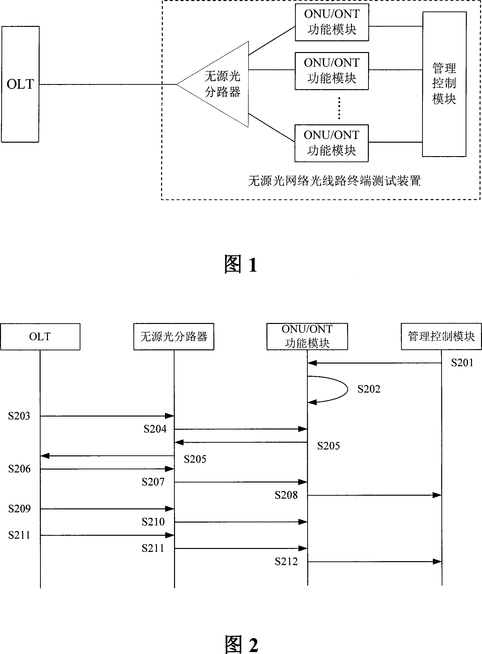
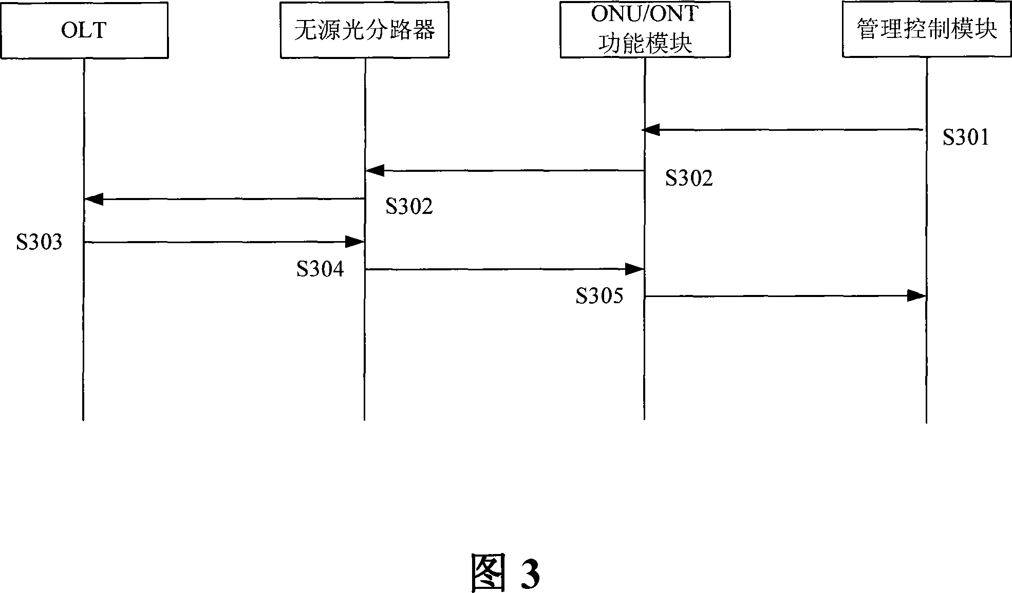
[0029] An OLT test device includes a passive optical splitter, multiple ONU / ONT function modules and a management control module. The test method of the OLT test device includes the following steps:

[0030] Step 1. Configure parameters for each ONU / ONT function module through the management control module according to the user's test requirements;

[0031] Step 2. Each ONU / ONT function module performs the serial number acquisition and ranging test process according to the configuration of the management control module. The serial number acquisition and ranging process is implemented in accordance with the relevant ITU G.984 standards. Each ONU / ONT The data sent and received by the functional module are multiplexed and separated by the passive optical splitter, and the status and statistical information of the serial number acquisition and ranging are sent to the management control module;

[0032] Step 3. After the serial number acquisition and ranging test process is completed, ...


PUM


Abstract

The invention discloses a measuring method of an optical circuit terminal of a passive optical network and comprises the following steps: step one, a functional module of an optical network unit or an optical network terminal is configured through a management controlling module; step two, the functional module of the optical network unit or the optical network terminal implements a testing process according to the configuration, and the testing process includes receiving the data that is outside a device and isolated by a passive optical splitter and or sending the data to be sent to the outside of the device to the passive optical splitter, thus reusing the sending; step three, the passive optical splitter implements splitting on the received data outside the device and/or reuses the data inside the device for sending thereof to the outside of the device, thus implementing a method which is simpler and only needs one optical fiber to be connected with the optical circuit terminal, avoiding the wire connection between each optical network unit or each optical network terminal, being convenient for users to operate and use, and leading the user operations of each optical network unit or each optical network terminal to be finished in a united platform interface.

Description

Technical field [0001] The invention relates to the field of optical line terminals in a passive optical network system, and in particular to a testing device and method for a passive optical network optical line terminal. Background technique [0002] With the development of broadband access technology, passive optical network is regarded as a very important broadband access technology. Its biggest advantage is that it does not require any active devices between the local exchange and users. A passive optical network system usually consists of an optical line terminal OLT on the office side, an optical network unit / optical network terminal ONU / ONT on the user side, and an optical distribution network ODN, and usually adopts a point-to-multipoint network structure. ODN is composed of single-mode fiber, optical splitter, optical connector and other passive optical devices, which provide optical transmission medium for the physical connection between OLT and ONU / ONT. [0003] In th...

Claims


Application Information

Patent Timeline
IPC IPC(8): H04B10/08H04J14/02H04B10/071H04B10/079
Inventor 孙智溢王康戴瑞春夏顺东
Owner ZTE CORP
Why Eureka
Try Eureka