
Device for producing a spun-bonded non-woven

A technology for monitoring devices, polymers, applications in measuring devices, textile and paper making, material analysis using acoustic/ultrasonic/infrasonic waves, etc.

Inactive Publication Date: 2008-07-09
OERLIKON TEXTILE GMBH & CO KG
View PDF3 Cites 8 Cited by
  • Summary
  • Abstract
  • Description
  • Claims
  • Application Information

AI Technical Summary

Problems solved by technology

Measurement results are therefore immediately available without delay in the event of possible process changes

Method used


Image

  • Device for producing a spun-bonded non-woven

Examples


Embodiment Construction

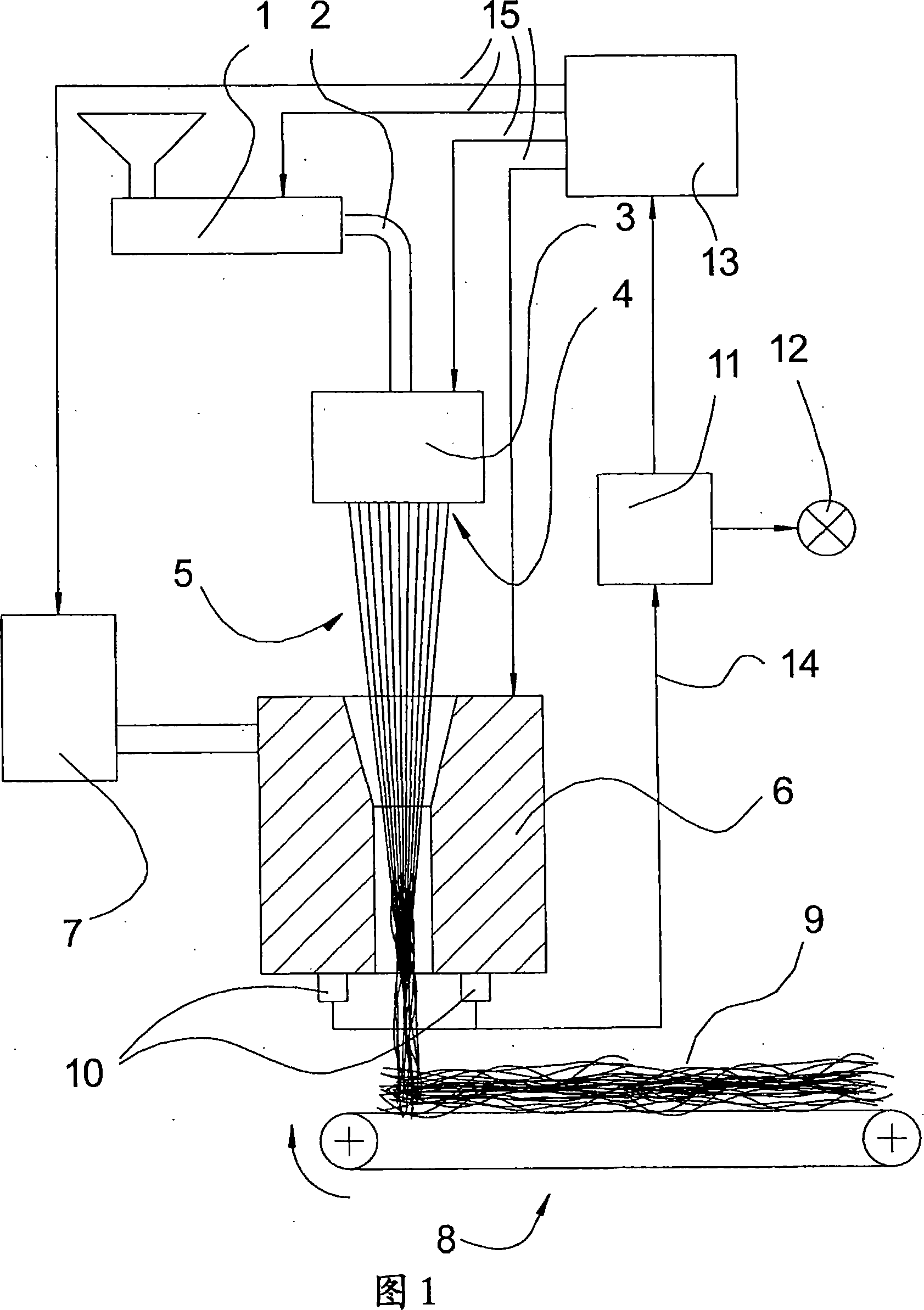
[0026] FIG. 1 shows an apparatus for melt spinning according to the present invention, which is an apparatus for producing spunbond nonwoven fabrics in this embodiment. From a melt source 1 , for example an extruder, the polymer in molten state is fed to a spin beam 3 via a melt line 2 . The spin beam 3 extends perpendicular to the plane of the drawing over a width approximately corresponding to the width of the spunbond nonwoven to be produced. On its underside, the spin beam 3 has a plurality of spinneret holes 4 through which the molten polymer is fed under high pressure and formed into filaments 5 . The internal structure of the spinning beam 3 with distribution lines, a spinning pump for increasing the pressure and a heating device is known from the prior art.

[0027] The monofilaments 5 emerging from the spinning beam 3 are arranged perpendicular to the plane of the drawing in the shape of a curtain and are fed to a drawing nozzle 6 . The draw-off nozzle 6 also extend...


PUM


Abstract

The present invention relates to an apparatus for producing spunbonded nonwoven fabrics. The molten polymer fed into the spinning beam from the melt source is extruded through a plurality of linearly arranged spinneret holes into monofilaments arranged in a curtain shape. A pulling force is applied to the monofilament by means of a pulling nozzle. The monofilaments are then deposited on a conveyor belt where they form a spunbond nonwoven fabric. A monitoring device is arranged on the pulling nozzle, which measures characteristic values ​​characterizing the machining process. One or more structure-borne sound sensors are preferably used as monitoring means. The measurement results of the monitoring device are compared with setpoint values ​​and fed to a signaling device or used to regulate the machining process.

Description

technical field [0001] The invention relates to a device for melt spinning and drawing of monofilaments according to the preamble of claim 1 and to a device for melt spinning and drawing of monofilaments according to the independent co-claims method of the preamble. Background technique [0002] A device of this type is known from WO 97 / 35053, in this case for producing spunbond nonwovens. Here, the molten polymer input by an extruder is spun into a plurality of monofilaments through one or several rows of nozzle holes arranged linearly in the spinning box. By means of a slit-shaped drawing nozzle arranged at a distance below the monofilament, a traction force is exerted on the monofilament, which draws and transports the monofilament. For this purpose, compressed air flows from the inner wall of the drawing nozzle in the direction of conveying the filaments, thereby exerting the desired pulling force on the filaments. The monofilaments are laid loose on a conveyor belt a...

Claims


Application Information

Patent Timeline
Patent Type & Authority Applications(China)
IPC IPC(8): D01D11/00G01N29/00B29C48/92
CPCD01D11/00G01N33/365B29C48/92B29C48/05B29C2948/92161B29C2948/92314B29C2948/92428B29C2948/92657B29C2948/9279B29C2948/92923
Inventor M·申肯H·拉威H·舍特勒A·默沙莫尔
Owner OERLIKON TEXTILE GMBH & CO KG
Learn More