Exterior lifting and pressing type ream bit for solum hole

A technology for reaming drill bits and soil layers, which is applied in the direction of drill bits, earthwork drilling, drilling equipment, etc. It can solve the problems of high failure rate, complicated drill mechanism, and high cost, and achieve low failure rate, few drill expansion mechanisms, and simple form Effect

Active Publication Date: 2008-07-16
XIAN RES INST OF CHINA COAL TECH& ENG GROUP CORP
View PDF0 Cites 7 Cited by
  • Summary
  • Abstract
  • Description
  • Claims
  • Application Information

AI Technical Summary

Problems solved by technology

[0005] The present invention provides a lifting and pressing type reaming drill bit outside the soil lay

Method used


Image

  • Exterior lifting and pressing type ream bit for solum hole
  • Exterior lifting and pressing type ream bit for solum hole
  • Exterior lifting and pressing type ream bit for solum hole

Examples


Embodiment 1

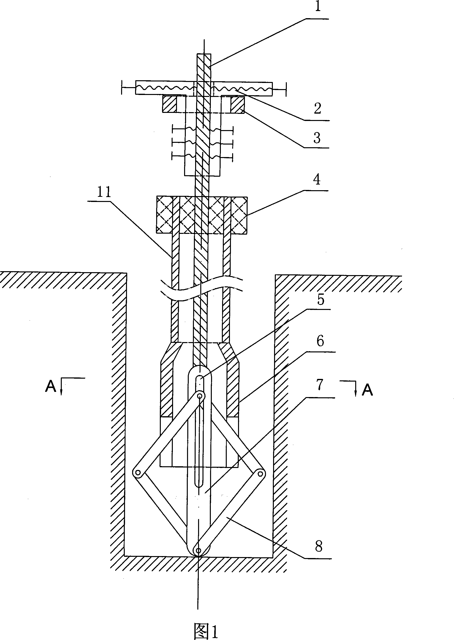
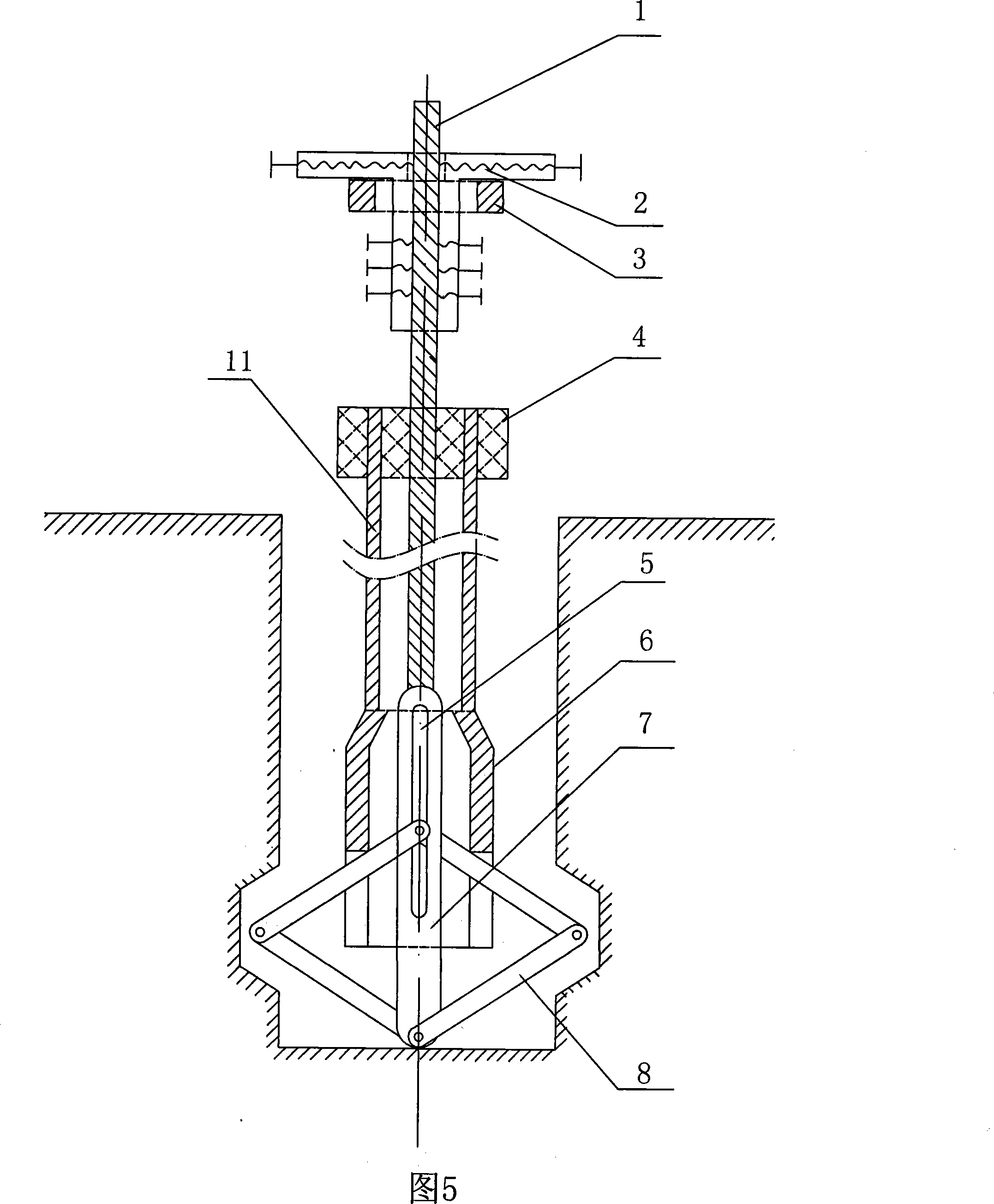
[0024] Embodiment 1: Referring to FIG. 1 to FIG. 4 , a lifting and pressing type reaming drill bit outside a soil layer hole includes a drill power head 4 , a drill pipe 11 , a drill body and a tie rod 1 . Said drill head 4 is connected with the drill rod 11, the drill rod 11 is connected with the drill bit body 6, and the tie rod 1 movably penetrates the drill rod 11 and the drill bit body. The upper part of the pull rod 1 is provided with a rotating bracket, which includes a pressure bearing 3 and a pull rod clamp 2 arranged on the pressure bearing 3, the pull rod 1 is fixed in the pull rod clamp 2 and is located at the center of the pressure bearing 3 . Said pull rod clamping part 2 is a "T" type casing, and jackscrews for fixing the pull rod 1 are provided on the wall of the vertical tube and at both ends of the horizontal tube. The pressure bearing 3 in the rotating support is fixedly arranged on the external support.

[0025] Said drill bit body comprises drill bit bod...

Embodiment 2

[0026] Embodiment 2: Referring to Fig. 1 to Fig. 4, the present invention can be implemented with the help of existing drilling equipment.

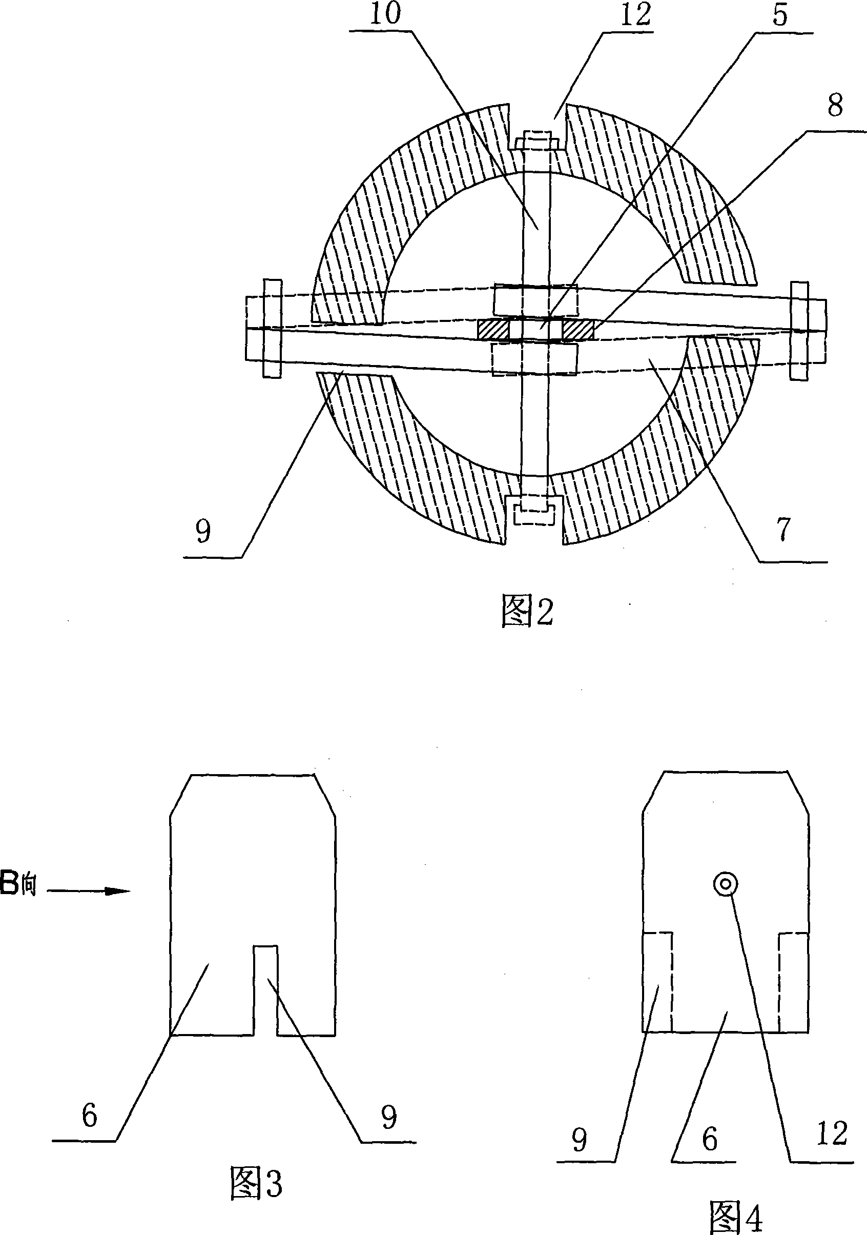
[0027] Place the expansion fins of the planar four-bar linkage mechanism 8 in the expansion notch 9 on the drill body 6, and connect its upper contact and sliding piece 7 to the lower push rod 10. When connecting, the lower push rod 10 passes through the upper contact and the sliding piece. The diffuser groove 5 of the sheet 7 is vertical to the plane controlled by the expansion notch 9 and fixed on the drill body 6; the expansion fins and the reaming fins are connected, and the lower contact of the reaming fins is connected to the sliding plate 7. on the lower endpoint. Connect the sliding plate 7 and the pull rod 1, the drill body 6 is connected to the bottom of the drill rod 11, and the pull rod 1 passes through the center of the drill rod 11 and passes through the upper end hole of the drill rod.

[0028] The upper end of the drill p...


PUM

PropertyMeasurementUnit
Elongationaaaaaaaaaa

Abstract

The invention relates to the technical field of boring tool in the industry of geotechnical engineering, in particular to an outer soil layer bore pressure-raised type broaching bit. This invention aims at overcoming the problems of the existing technology such as the complex structure of bit, high cost, high failure rate, etc. To overcome the problems of the existing technology, the technical proposal of this invention is that: an outer soil layer bore pressure-raised type broaching bit includes a power unit of a drilling machine, a drill stem and a bit body, wherein the drill stem is fixed in the power unit; the device additionally includes a drawbar which can movably pass through the power unit of the drilling machine, the drill stem and the bit body, and a swinging strut is arranged at the upper part of the drawbar; the bid body includes a bit body and a planar four bar linkage mechanism. Compared with the prior art, the invention has the advantages that: 1. The bit broaching mechanism is less and the structure is simple; 2. The accuracy requirement on the subassembly is not high, thus being easy for manufacturing; 3. the bit cost is low and the economic benefits is good; 4. The stretch and the shrinkage of the bit is easy and the failure rate is low.

Description

Technical field: [0001] The invention relates to the technical field of drilling tools in the geotechnical engineering industry, in particular to a pressure-lifting type reaming drill bit outside a hole in a soil layer. Background technique: [0002] In the geotechnical engineering industry, such as foundation reinforcement under building caps, etc., it is often encountered in drilling projects that need to drill down into and out of large-diameter drill holes in the upper small-diameter boreholes. Normal drills cannot form holes and need to be expanded. A hole drill will get the job done. [0003] The feature of the existing reaming drill is that the reaming device of the drill is in the hole, and the reaming function of the drill is realized in the hole. [0004] Because the reaming device and function of the drill bit are realized in the hole, the defects of the existing reaming drill bit are: 1. The drill bit expansion mechanism is complicated, the manufacturing process...

Claims


Application Information

Patent Timeline
IPC IPC(8): E21B10/32
Inventor 姬中奎张群刘其声靳秀良靳德武王新夏宇靖柴建禄
Owner XIAN RES INST OF CHINA COAL TECH& ENG GROUP CORP
Why Eureka
Try Eureka